WARNING: FOR YOUR OWN SAFETY ALWAYS
LOCK THE SWITCH "OFF" WHEN SAW IS NOT
IN USE. REMOVE KEY AND KEEP IT IN A SAFE
PLACE . . . ALSO IN THE EVENT OF A POWER
FAILURE (ALL YOUR LIGHTS GO OUT) TURN
SWITCH OFF. LOCK IT AND REMOVE THE KEY
THIS WILL PREVENT THE SAW FROM
STARTING UP AGAIN WHEN THE POWER
COMES BACK ON.
7. The Manual Motor Brake.
a. The manual brake is located on the motor shaft at
the right-hand end of motor.
la. Pressing on the brake button with finger or thumb,
after turning off the ON-OFF switch, will greatly
reduce blade coasting time.
8. Accessory Shaft.
NOTE: When using an accessory such as a drill chuck
attached to end of motor shaft, it will be necessary to
remove the accessory shaft cover.
CAUTION: Motor spacer, both blade collars and shaft nut
must be installed when using accessory shaft.
Be sure to re-install the accessory shaft cover
after removing the accessory.
Use only the following recommended accessories:
Drill chuck, Sanding drum, and Router adapter.
CAUTION: The sawblade, dado, or cutting tool must
be removed from the saw arbor before using the
accessory shaft. NEVER operate the saw with cutting
tools (including sanding accessories) installed on both
ends of the saw arbor.
POSITIONING GUARD, ANTIKICKBACK AND
SPREADER ASSEMBLY, FOR RIPPING
WARNING: NEVER POSITION THE GUARD OR
ANTIKICKBACK ASSEMBLY WITH THE POWER
ON. NEVER POSITION THE ANTIKICKBACK
PAWLS BY GRASPING THE PAWLS OR
SPREADER.
_) GUARD
'NFEED _l EO_K __ O UsTFEEED
DIRECTION
NOSE OF J MINIMUM
GUARD GUARD CLEARANCE
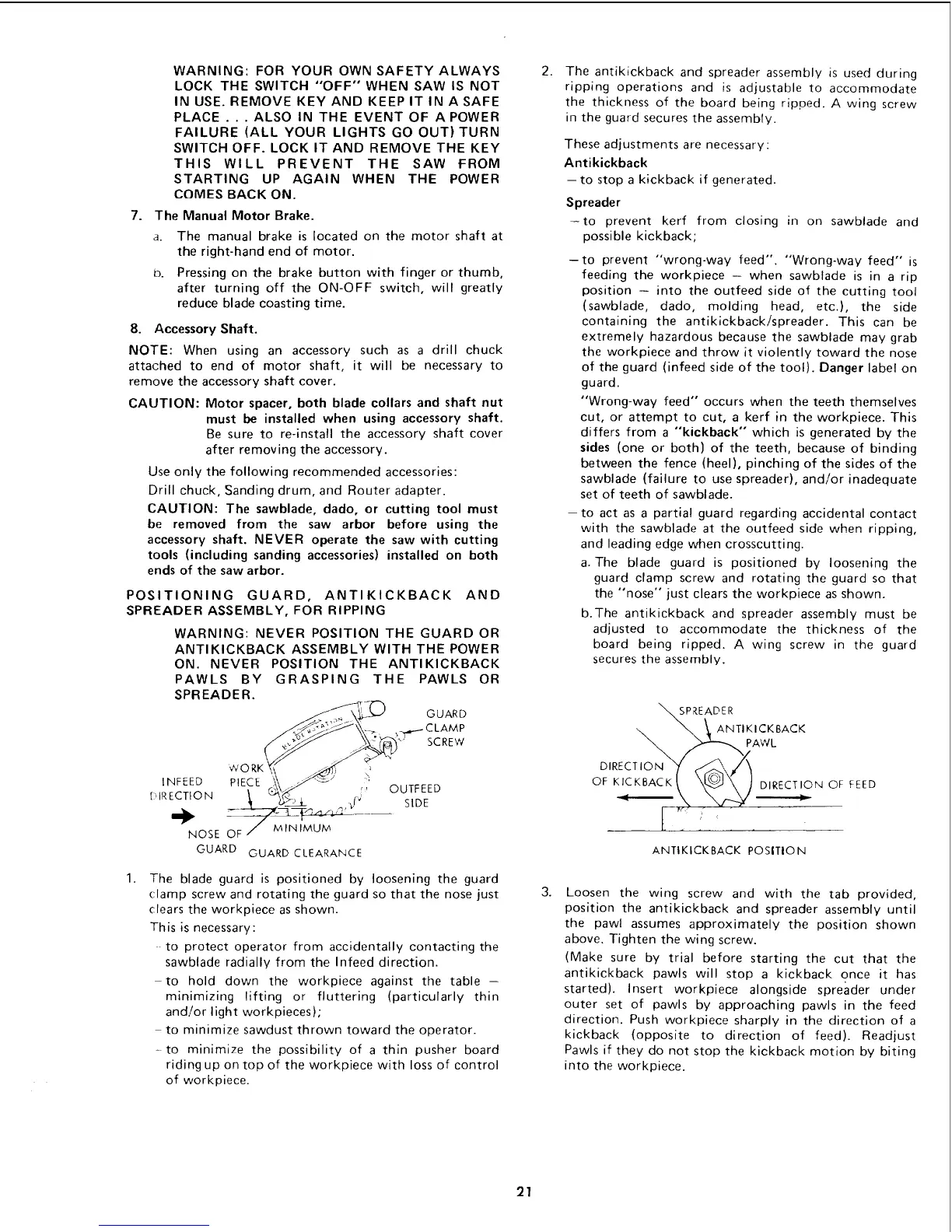
1.
The blade guard is positioned by loosening the guard
clamp screw and rotating the guard so that the nose just
clears the workpiece as shown.
This is necessary:
to protect operator from accidentally contacting the
sawblade radially from the Infeed direction.
to hold down the workpiece against the table -
minimizing lifting or fluttering (particularly thin
and/or light workpieces);
to minimize sawdust thrown toward the operator.
- to minimize the possibility of a thin pusher board
riding up on top of the workpiece with loss of control
of workpiece.
2.
The antikickback and spreader assembly is used during
ripping operations and is adjustable to accommodate
the thickness of the board being ripped. A wing screw
in the guard secures the assembly.
These adjustments are necessary:
Antikickback
-- to stop a kickback if generated.
Spreader
-to prevent kerf from closing in on sawblade and
possible kickback;
-to prevent "wrong-way feed". "Wrong-way feed" is
feeding the workpiece -- when sawblade is in a rip
position -- into the outfeed side of the cutting tool
(sawblade, dado, molding head, etc.), the side
containing the antikickback/spreader. This can be
extremely hazardous because the sawblade may grab
the workpiece and throw it violently toward the nose
of the guard (infeed side of the tool). Danger label on
guard.
"Wrong-way feed" occurs when the teeth themselves
cut, or attempt to cut, a kerf in the workpiece. This
differs from a "kickback" which is generated by the
sides (one or both) of the teeth, because of binding
between the fence (heel), pinching of the sides of the
sawblade (failure to use spreader), and/or inadequate
set of teeth of sawblade.
-to act as a partial guard regarding accidental contact
with the sawblade at the outfeed side when ripping,
and leading edge when crosscutting.
a. The blade guard is positioned by loosening the
guard clamp screw and rotating the guard so that
the "nose" just clears the workpiece as shown.
b.The antikickback and spreader assembly must be
adjusted to accommodate the thickness of the
board being ripped. A wing screw in the guard
secures the assembly.
DIRECT%
OF KICKBACK
SPREADER
ANTIKICKBACK
PAWL
DIRECTION OF FEED
ANTIKICKBACK POSITIO N
3.
Loosen the wing screw and with the tab provided,
position the antikickback and spreader assembly until
the pawl assumes approximately the position shown
above. Tighten the wing screw.
(Make sure by trial before starting the cut that the
antikickback pawls will stop a kickback once it has
started). Insert workpiece alongside spreader under
outer set of pawls by approaching pawls in the feed
direction. Push workpiece sharply in the direction of a
kickback (opposite to direction of feed). Readjust
Pawls if they do not stop the kickback motion by biting
into the workpiece.
21
 Loading...