Operation Manual
CTs Power Amplifiers
page 40
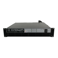
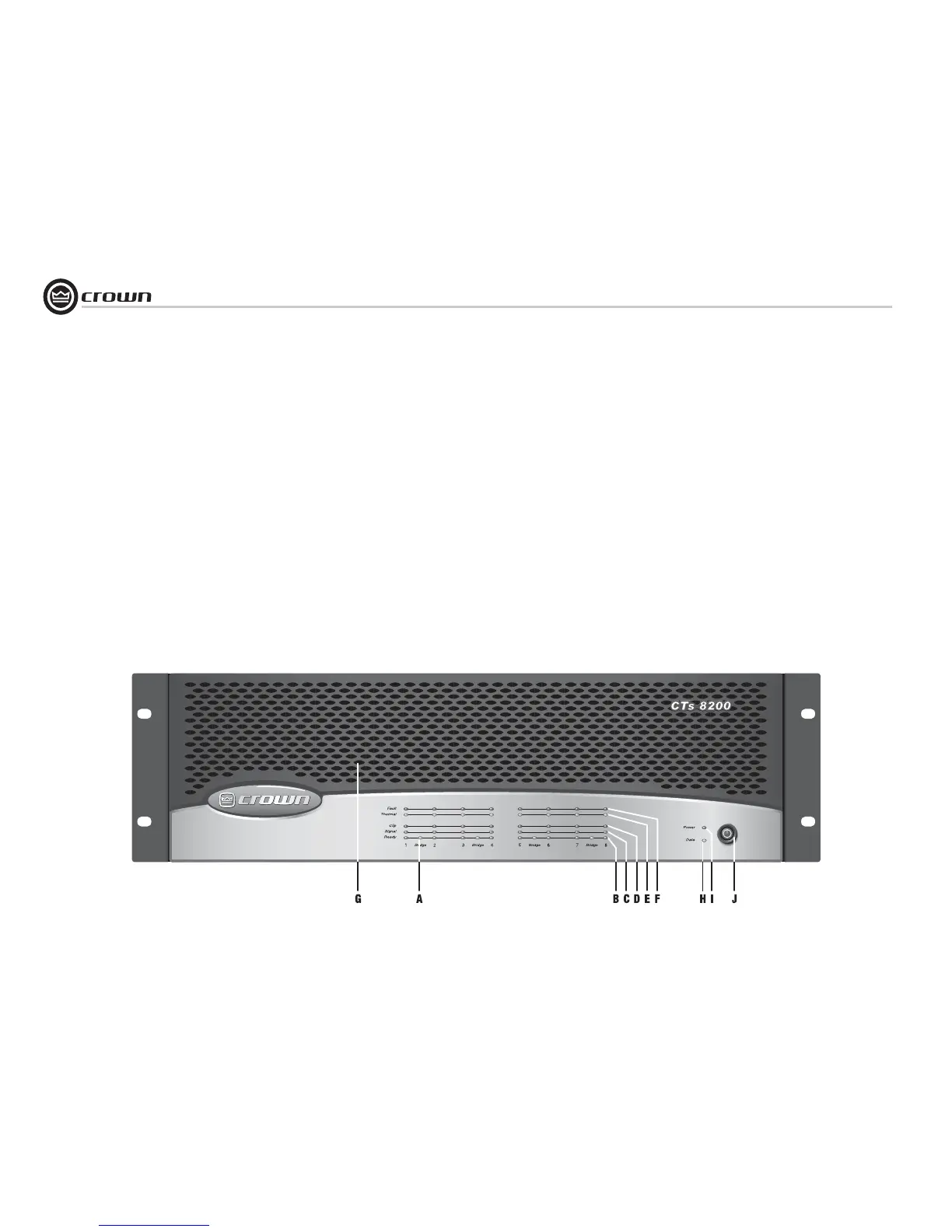
4.2 Front Panel Controls
and Indicators
Note: CTs 8200 is shown. Some CTs
4200 features are in different locations.
A. Bridge Mode Indicator
Yellow LED, one per channel pair, illumi-
nates when the channel pair's Mode
Switch is set to the “Bridge” position. If
Mode switch is changed while amplifier is
powered up, Bridge LED will flash, indicat-
ing that the amplifier must be powered off
and on to reset the Mode. See Section 6.9.
B. Ready Indicator
Green LED, one per channel, illuminates
when the channel is initialized and ready to
produce audio output.
C. Signal Indicator
Green LED, one per channel, illuminates to
indicate the presence of input signals
above –40 dBu.
D. Clip Indicator
Red LED, one per channel, illuminates
when the THD of the channel’s output sig-
nal rises to a level typically considered as
the onset of audible clipping. The Clip
Indicator also will illuminate during Ther-
mal Level Control (TLC) or input overload.
E. Thermal Indicator
Red LED, one per channel, flashes when
the channel has shut down due to thermal
stress or overload. If the power supply
goes into thermal overload, all channel
LEDs will flash.
F. Fault Indicator
Red LED, one per channel, illuminates
when the amplifier output channel has
stopped operating.
G. Ventilation Grille
Front-to-rear forced airflow.
H. Data Indicator
Yellow LED indicates IQ Loop data activity
(if the amplifier is equipped with an IQ-MC
module, and connected to an IQ Loop).
I. Power Indicator
Blue LED indicates amplifier has been
turned on and AC power is available. Indi-
cator also flashes if the amplifier shuts off
due to an under/over-voltage condition on
the AC mains.
J. Power Switch
Amplifier is on when the switch is in the IN
position.
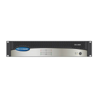
Figure 4.1 CTs 8200 front panel.
4 Operation
 Loading...