Operation Manual
CTs Power Amplifiers
page 44
Choosing the Right Module
To order accessory modules for your amplifier,
please refer to the model tag (located on the back
panel of the amplifier) for your amplifier’s specific
model number. Then refer to the chart below to
select the correct accessory for your requirements.
VCA MODULE
CTs 4200 VCA-MC4
CTs 4200A VCA-MC4A
CTs 8200 VCA-MC8
CTs 8200A VCA-MC8
Wall-Mount level control panels for use with
VCA module:
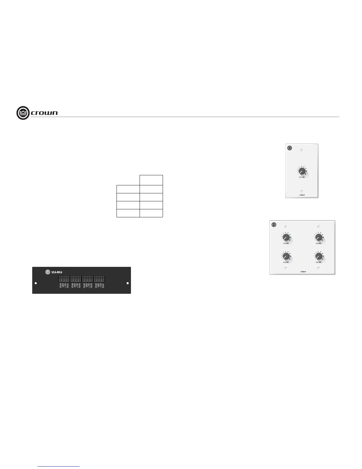
1-VCAP: See Figure 5.4. Used in conjunction with
a VCA-MC module, this is a single-gang panel pro-
viding remote volume control for one or more CTs
amplifier channels. The potentiometer on the panel
is wired directly to one of the VCA connectors on
the VCA-MC.
4-VCAP: See Figure 5.5. This is a two-gang panel
providing remote volume control for four or more
CTs amplifier channels. The potentiometers on the
panel are wired directly to the respective VCA con-
nector on the VCA-MC.
Refer to the VCA-MC Operation Manual for wiring
of the single or multiple channel level control.
Your amplifier may have come with a VCA-MC
module already factory-installed, or your choice of
MC modules can be easily added to the amplifier by
any authorized Crown Service Center. Contact
Crown Technical Support for more details.
5.3.2 Input Sensitivity
The CTs 4200 and CTs 8200 have a fixed input sen-
sitivity of 1.4V. A service option is available for
other input sensitivities.
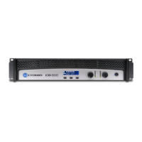
Figure 5.3 VCA-MC8 Module
Figure 5.5 4-VCAP Module
5 Advanced Features
and Options
Figure 5.4 1-VCAP Module
5.3 Options
Below are some available options. For current
options, visit the Crown website at www.crownau-
dio.com.
5.3.1 Control Modules
VCA-MC (VCA module): See Figure 5.3. Pro-
vides independent remote level control for each
channel. 4-pin removable Phoenix-style barrier
connectors provide the +10VDC control voltage,
ground, and control lines for two amplifier chan-
nels. Thus, 4-channel amplifiers use two connec-
tors; 8-channel amplifiers use four connectors.
 Loading...