capabilities. The limit point
is
deltnnincd
by
a
co
mbination
of
the predriver
plu
s limiter current equaling
the
available current
source
on
the
main
board.
In
ollier
words,
the
signal drive that is
fed
to
the
predrivers is
limited or clamped.
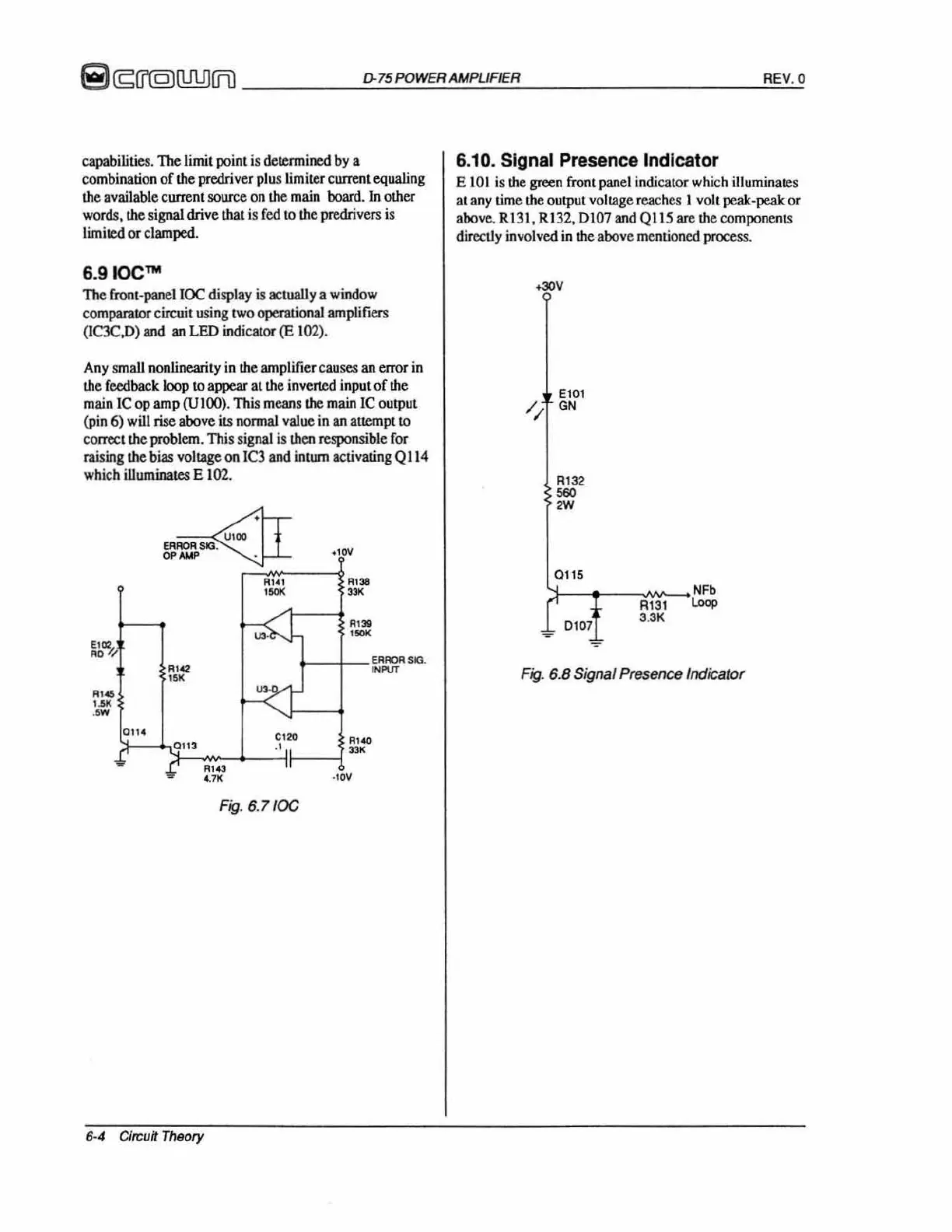
6.
9IOe'"
The front-panellOC display
is
actually a window
comparator circuit
using
two
operationaJ
amplifiers
(IC3C.D)
and
an
LED
md;cator
(E
102).
Any
small
nonlinearity
in
the
amplifier causes
an
error
in
lIIe
feedback loop
to
appear at
lIIe
inverted input of
th
e
main
ICop
amp
(UIOO).
This
means
th
e
main
Ie
output
(pin
6)
will
rise
above i
ts
nonnal value
in
an
attempt to
com:ct the
problem
. This signal is
lhen
respons
ibl
e
for
raising the bias
vo
ltage
on
IC3
and
intwn activating
QI14
wh
ich
iUuminates
E 1
02.
,,,.
,~
>w
""
''''
""
<~
Fig
. 6
.l
/OC
6·4
Circuit
Theory
''''
,
"'"
1-_+-
_I:
F1ROR
sn.
'
N""
·
10\1
6.10. Signal Presence Indicator
E
101
is
lII
e green
front
panel
indlcatorwhich illuminates
at
any
time
lII
e output voltage reaches I volt peak-peak
or
above.
RI31, R132,
0107
and
QI15
are
Lhecomponents
directly involved
in
the above mentioned process.
~
El01
GN
R132
""
2W
0115
0107
~
NF'
Rl31
lDop
3.
3K
Fig
. 6.8 Signal Presence Indicator
 Loading...