@
~(j'(Q)(lMa=u
_____
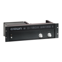
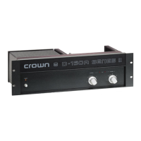
"D-.::75"'P--'O'-'W"'E"'R.::A:::M:.:PL:::'F.::'E::.R'---
_________
--'-R"'E-"V
-
.::
0
inductive
load
which causes the
load
to emanate a
pulse.
This returned
indu
ctive e
ner
gy
has
the opposite polarity
or
th
e origi
nal
pulse· hence
lhe
nam
e "flyback"
pul
se.
It
resu
l
ts
in
a rasping, popping distortion
which
is
very
irril.a
lin
g.)
Because
the
currcOl
limit
er
of
the
D-75
will
nOI
yie
ld
to the
constant curre
nt
demands of an inductive l
oad
but
will
suSl.ain
them, it
is
immune
to
flyback distortion.
Early amplifier designs frequently
emp
loyed
fixed
current
limiters, reducing fiyback transients, but had serious
difficulty
oblaining reliable l
ow
frequency output -
especia
ll
y at full-voltage into 4 ohm loads.
In
addition.
many
early
de
signs u
sed
fragile
cpi
-ba
se
or triple-diffused
outputs which mat
ed
poorly
10
the current limiting
protection schemes
used
and
resuhcd
in
low
pcrfonnancc.
The
D-75
uses
two
multiple epitaxial silicon power
U"ansistors
per channel. Their toughness a
ll
ows
the
reliable
use
ofa current limiler. A
nd
since limiting
is
adjusted to the
spectral conte
nt
of
the
signal,
much
larger power
ou
tput
s are
safely achieved.
At
subsonic [rcquencies,
it
behaves
as
a VI limiter
and
provides
the
increased
proteCtion
needed
to prevent
destruction due to excessive
heat
build-up
in
the
half
of
the
outpu
t stage that is
be
in
g driven.
DC
applied to the i
nput
should never cause accidental
loudspeaker damage because
of
a input coup
lin
g capacito
r.
All
the
amplifier's voltage-amplifier circ
ui
try
is
designed
to
8-2 Appendix 8
be
inh
erently current-limited. Thereby, if
any
of
the
de
vices
should
fa
il
(which
is extremely
un
lik
el
y)
no
damage
will
occur
to
the
rest of
the
stages.
The
AC
line
for
IOO
or
120
V
is
fused
with
a 2 A
fuse.
For
200,2200r240VAC,a I A
fuse
is
used.
Theuseofanyother
type
or size
fuse
will
invalidate the warranty.
The inp
ul
stage
is
protected against excessi
ve
input si
gnal
l
eve
l (overdrive)
by
a series-limiting resistor.
The amplifier
fcalUresa
controlled
slew
rate
which,
coupled
with
the
prolCCtion
circuilS,
guards
the
amplifier
from
blowups
when
fed
lar
ge
RF input signals.
6.4 Fuse Replacement
An
AC
linefuse
is
located next to
the
power cord
on
the
back
panel
of
the
amplifier.
To
replace
the
fuse.
first
TURN
OFF
THE
POWER
SWITCH
AND
DISCONNECT THE
POWER
PLUG
FROM
THE
POWER
SOURCE.
Unscrew
the
cap of
the
fuse
holder
and
remove
the
fusc.
Replace
the
fuse
wit
h a 2
amp
fuse
for
100 or
120
VAC
operation
and
a 1
amp
fuse
for
200, 220 or
240
VAC
operation. Reassemble
in
reverse order.
IMPORT
ANT:
The
fuse
holder sl
ill
has
power
eve
n
when
the
power switch
is
tu
rned
off.
ALWA
YS
DISCONNECT
AC
POWER
BEFORE REPLACING
FUSES_
 Loading...