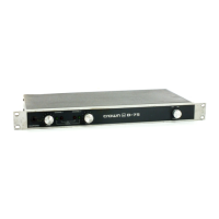
ill ustration
1
.1
0·75
...................................................... ..
2.
1 Front Facilities (0.75) ................................ .
2.2 Rear Facilities
(0·75) ............ ..................... .
4
.1
2 Ohm Load Wavefonn ............................. ..
4.2
10KHz Square
Wave
.................................. .
4
.3
20KHz Sine
Wave
..................................... .
4.4
1M
Distortion Test Se(·up .......................... ..
4.5
Signal
to
Noise Test Set·up ........................ ..
5.1
AC
Mains Voltage Conversion ... _ ............... ..
6.1
0-
75
Block Diagr$l .................................. .
6.2 Balanc
ed
Input
Sta~e
................................. .
6.3
In
put Operati
onal
Amplifier. ....................... ..
6.4
Signal
Translato
r .............................
...
......
..
6.5
Final
Voltage.Amplifier
..
..................
..
.......
..
,
.,
2·'
2·2
4·)
4-3
4·)
44
44
5
·1
6-1
6-2
6·2
6·2
6-3
6.6 Bias, Output
and
Protection Stages................. 6·3
6.7
IOC ........................................................
64
6.8 Signal Presence Indicator ............................ .
7.1
Power
Matrix
..........................................
..
7.2
Nominal Frequency Responce .....................
..
7.3
Nominal Output Impzdance. ....................... ..
7.4
Nominal
Phase
Respon
ce ........................... ..
7.5
Nominal Power Efficien
cy
.......................... .
7.6 Nominal Damping Factor ..........................
..
7.7
Nomi
nal
Output Phase Angle ....................... .
7.8
Nominal
Crosstalk. ........ ............................ .
7.9
Nominal Noise Spectrum ....................
..
...... .
8.1
0-
75
Schematic Diagrams ..............
..
........... .
9.
1
0-
75
Main
Modules .................................. ..
9.2
Output
Modu
l
e<
......................................... .
9.3
D-75
Front
Pan
el Assernbly ......................... .
9.4
0-75
Neon
Bracket Assembly .................... ..
9.5
0·75
Back
Panel
Assembly ......................... .
9.6
D-7
5
Ca
pa
ci
tor
Bracket
Asse
mbl
y ............... ..
9.7
D
-75
Final
Assembly ................................ ..
A.1
0-
75
Mounting OimentiooS" ..................... ..
A.2
Input High
Pass
Filter .....
.. ..
....................... .
A.3
InpUi
Low Pass Filter ................................ .
A.4
Wire
Ga
u
ge
Nomograph
............................ .
A.5
Connection
to
an
Inductive
Load.
................ ..
A.6
Fuse
Nomog
r
aph
............................. ......... .
64
7·)
74
74
7·5
7·5
7·6
7·6
7·7
7·7
g·l
9·2
.3
9·9
9·11,
12
, I3
9·16
9·17
9- 19
9·20
A· I
A·2
A·2
A·3
A·3
A4

 Loading...