Series 1000 and 1500
67
34.27.Test run the tractor in a safe are that is free of
obstacles, hazards, and bystanders after the cut
-
ting deck is installed. Check all safety features
before returning the tractor to service.
35. STEERING GEAR AND STEERING PINION
GEAR REPLACEMENT
NOTE: If you are replacing the steering gear or
steering pinion gear, check the condition of both
gears for any wear or damage. It may be wise to
replace both as a set.
35.1. Remove the cutting deck. See cutting deck
removal section.
35.2. If you are just replacing the steering pinion gear,
use a 11/16” socket to remove the flange lock
nut securing the steering pinion gear to the
steering shaft.
See Figure 35.2.
NOTE: If you are replacing the steering gear at
this time, continue with the following steps, oth
-
erwise install a new steering pinion gear and
reassemble in the reverse order of disassembly.
35.3. If you did not remove the PTO belt guard before
you removed the cutting deck, do so now.
35.4. Remove the drag links from the steering gear.
35.5. Disconnect the PTO electrical connector from
the wiring harness.
35.6. Using a 5/8” socket and impact wrench, remove
the bolt securing the PTO to the engine crank
-
shaft. Remove the PTO from the shaft.
35.7. Remove the drive belt from around the twin idler
pulleys. This will ease removal of the drive belt
from around the engine pulley.
Figure 35.2
Steering Pinion Gear
Flange Lock Nut
35.8. Lower the engine pulley on the crankshaft as
you remove the drive belt from around the pul
-
ley. Remove the pulley from the crankshaft. Note
the orientation of the pulley for later installation.
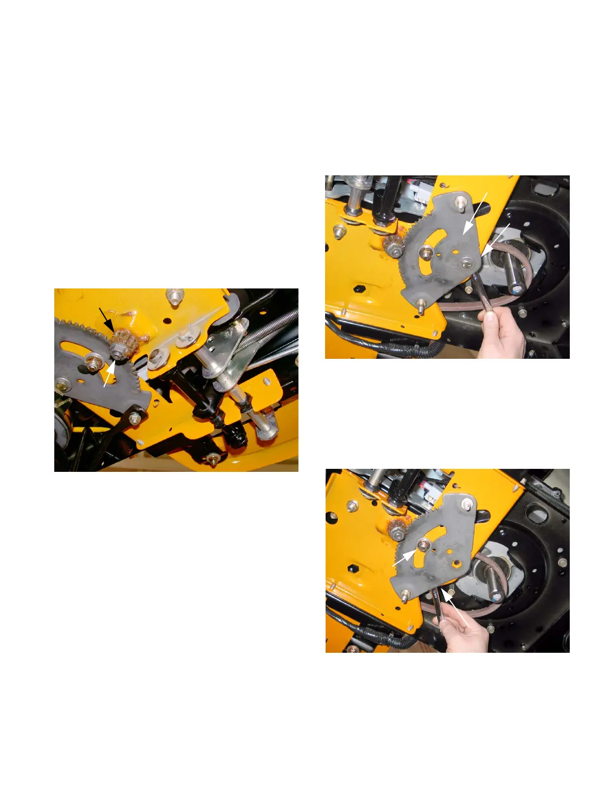
35.9. Place a 9/16” wrench on the lock nut that
secures the steering gear to the subframe. Using
a 14mm socket, remove the hex cap screw and
shoulder spacer.
See Figure 35.9.
NOTE: You may need to use an impact wrench
on this cap screw.
35.10.Using a 9/16” wrench and socket, remove the
hex cap screw, shoulder spacer and hex nut in
the middle of the steering gear. Remove the
steering gear.
See Figure 35.10.
35.11. Install in the reverse order of disassembly.
Figure 35.9
Steering Gear
9/16” wrench on
hex lock nut
Figure 35.10
9/16” wrench on hex cap screw
Shoulder Spacer
and Locking Hex Nut
 Loading...