xStack® DES-3200 Series Layer 2 Ethernet Managed Switch Hardware Installation Guide
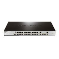
Rear Panel Description
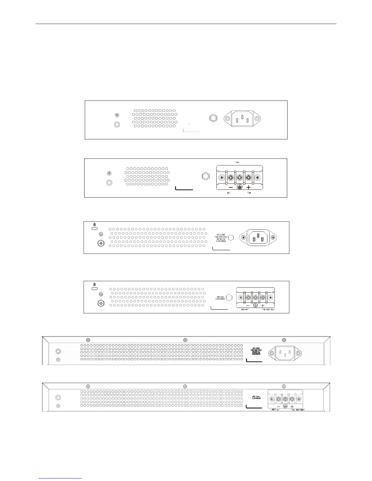
The rear panel of the Switch contains an AC or DC power connector. The AC power connector is a standard three-
pronged connector that supports the power cord. Plug-in the female connector of the provided power cord into this
socket, and the male side of the cord into a power outlet. The Switch automatically adjusts its power setting to any
supply voltage in the range from 100 to 240 VAC at 50 to 60 Hz. The DC power supply has a three-terminal wiring
block consisting of a positive (+), a negative (-) and a safety ground terminal. Connect the Kensington-compatible
security lock, at the rear of the switch, to a secure immovable device. Insert the lock into the notch and turn the key to
secure the lock.
AC LINE
100-240 VAC
50-60 Hz
0.
3AMAX
Figure 1-27. Rear panel view of the DES-3200-10
0.4A MAX
-48V -48V RET
-48 V
Figure 1-28. Rear panel view of the DES-3200-10-DC
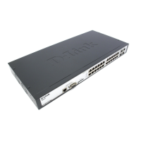
Figure 1-29. Rear panel view of the DES-3200-18
Figure 1-30. Rear panel view of the DES-3200-18-DC
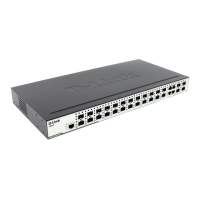
Figure 1-31. Rear panel view of the DES-3200-26
Figure 1-32. Rear panel view of the DES-3200-26-DC
11
 Loading...