ENGLISH
58
For correct operation the mains filter must be installed close to the Inverter!
2.3.1 Connection to the power supply for M/T and M/M models
The relative line specifications must correspond to those shown in Table 2.
The section, type and laying of cables for inverter power supply and electric pump connections must be selected in
compliance with current standards. Table 3 provides indications on the cable section to be used. The table refers to
cables in PVC with 3-core cable (phase neutral + earth)with the minimum recommended section based on the current
and length of cable.
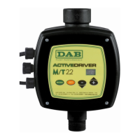
Power cable section in mm²
Data for 3-core PVC cables (phase + neutral + earth)
10 m 20 m 30 m 40 m 50 m 60 m 70 m 80 m 90 m 100 m 120 m 140 m 160 m 180 m 200 m
4 A
1,5 1,5 1,5 1,5 2,5 2,5 2,5 2,5 4 4 4 6 6 6 10
8 A
1,5 1,5 2,5 2,5 4 4 6 6 6 10 10 10 10 16 16
12 A
1,5 2,5 4 4 6 6 10 10 10 10 16 16 16
16 A
2,5 2,5 4 6 10 10 10 10 16 16 16
20 A
4 4 6 10 10 10 16 16 16 16
24 A
4 4 6 10 10 16 16 16
28 A
6 6 10 10 16 16 16
Table 3: Section of power cables for M/M and M/T inverters
The current supply to the inverter can generally by estimated (with a relative safety margin) at 2.5 times the current
absorbed by the three-phase pump. For example, if the pump connected to the inverter absorbs 10A per phase, the
inverter power supply cables should be sized for 25A.
Although the inverter is already equipped with internal safety devices, the installation of a suitably sized thermal
magnetic circuit breaker is recommended.
2.3.2 Connection to the power supply for T/T models
The relative line specifications must correspond to those shown in Table 2. The section, type and laying of cables for
inverter power supply and electric pump connections must be selected in compliance with current standards. Table 4
provides indications on the cable section to be used. The table refers to cables in PVC with 4 wires (3 phases+earth)
with the minimum recommended section based on the current and length of cable.
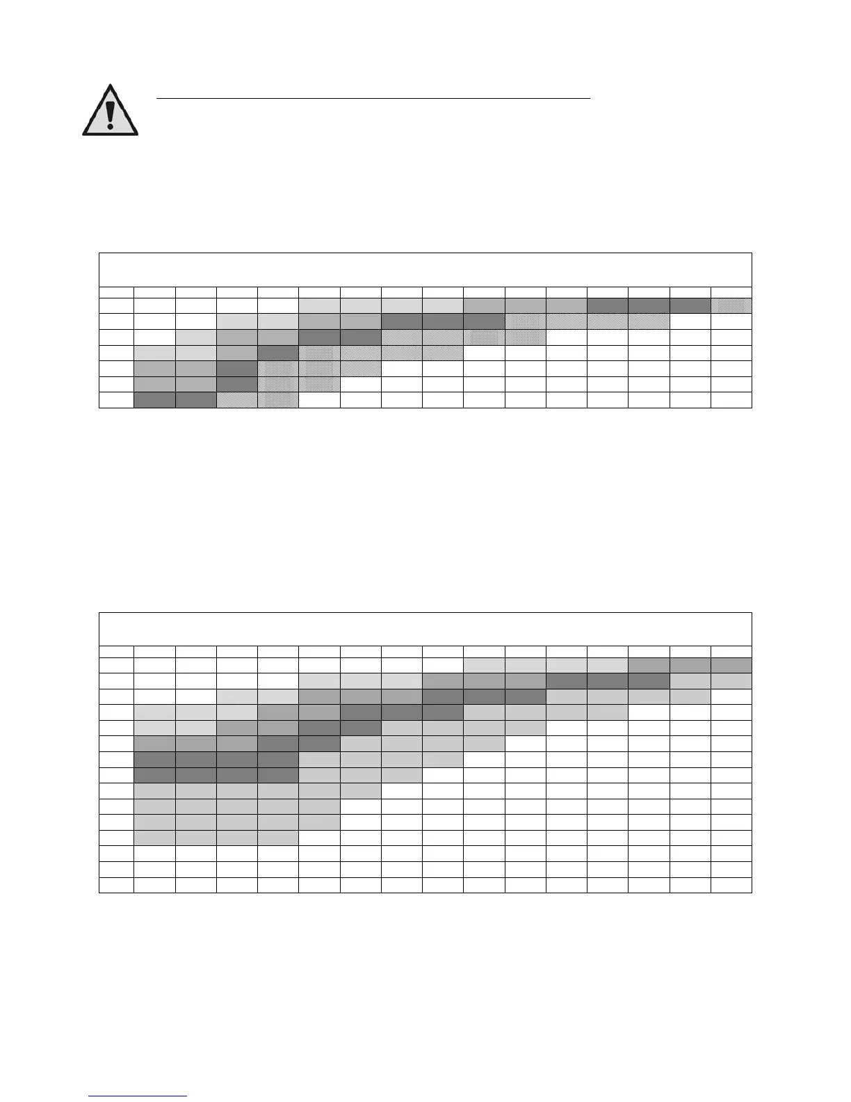
Cable section in mm²
Data for 4-core PVC cables (3 phases + earth))
10 m 20 m 30 m 40 m 50 m 60 m 70 m 80 m 90 m 100 m 120 m 140 m 160 m 180 m 200 m
4 A
1,5 1,5 1,5 1,5 1,5 1,5 1,5 1,5 2,5 2,5 2,5 2,5 4 4 4
8 A
1,5 1,5 1,5 1,5 2,5 2,5 2,5 4 4 4 6 6 6 10 10
12 A
1,5 1,5 2,5 2,5 4 4 4 6 6 6 10 10 10 10 16
16 A
2,5 2,5 2,5 4 4 6 6 6 10 10 10 10 16 16 16
20 A
2,5 2,5 4 4 6 6 10 10 10 10 16 16 16 16 16
24 A
4 4 4 6 6 10 10 10 10 16 16 16 16 16 16
28 A
6 6 6 6 10 10 10 10 16 16 16 16 16 16 16
32 A
6 6 6 6 10 10 10 16 16 16 16 16 16 16 16
36 A
10 10 10 10 10 10 16 16 16 16 16 16 16 16 16
40 A
10 10 10 10 10 16 16 16 16 16 16 16 16 16 16
44 A
10 10 10 10 10 16 16 16 16 16 16 16 16 16 16
48 A
10 10 10 10 16 16 16 16 16 16 16 16 16 16 16
52 A
16 16 16 16 16 16 16 16 16 16 16 16 16 16 16
56 A
16 16 16 16 16 16 16 16 16 16 16 16 16 16 16
60 A
16 16 16 16 16 16 16 16 16 16 16 16 16 16 16
Table 4: Section of 4-wire cable (3 phases + earth)
 Loading...