ENGLISH
61
Table 6: Input specifications
2.3.4 Connection of the user outputs
The user outputs are available only in type M/T and T/T inverters.
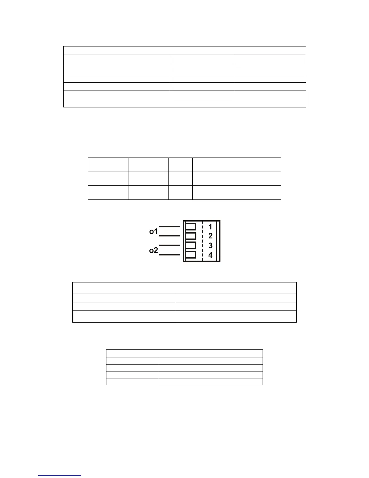
The wiring diagram and the electrical characteristics of the outputs are shown below.
User outputs wiring diagram
Type of
inverter
Name of
connector
Pin Output
M/T J13
1-2
Out 1
3-4
Out 2
T/T J6
1-2
Out 1
3-4
Out 2
Table 7: Output connection
Figure 3: Output connection
Output contact specifications
Type of contact NO
Max. admissible voltage [V] 250
Max. admissible current [A]
5 -> resistive load
2,5 -> inductive load
Table 8: Output contact specifications
2.3.5 Connection of the remote sensor
Connection of the remote sensor
Type of inverter Name of connector
M/T J8
T/T J10
M/M J6
Table 9: Connection of the remote pressure sensor
Input characteristics for type M/T and T/T inverters
DC inputs [V] AC inputs 50-60 Hz [Vrms]
Minimum activation voltage [V] 8 6
Maximum deactivation voltage [V] 2 1,5
Maximum admissible voltage [V] 36 36
Current absorption at 12V [mA] 3,3 3,3
N.B. Inputs can be controlled with both polarities (positive or negative with respective return to earth)
 Loading...