EDUS121503A Control Devices
Options 639
4
2.6 <KRP4A74> Wiring Adaptor for Electrical Appendices
Adaptor
Adaptor
Service monitor (H10P: Red)
×1
Service monitor (H1P: Green)
Transmission wiring (P1,P2)
SS2
Clamp
(Ex.)When individually controlling 8 units
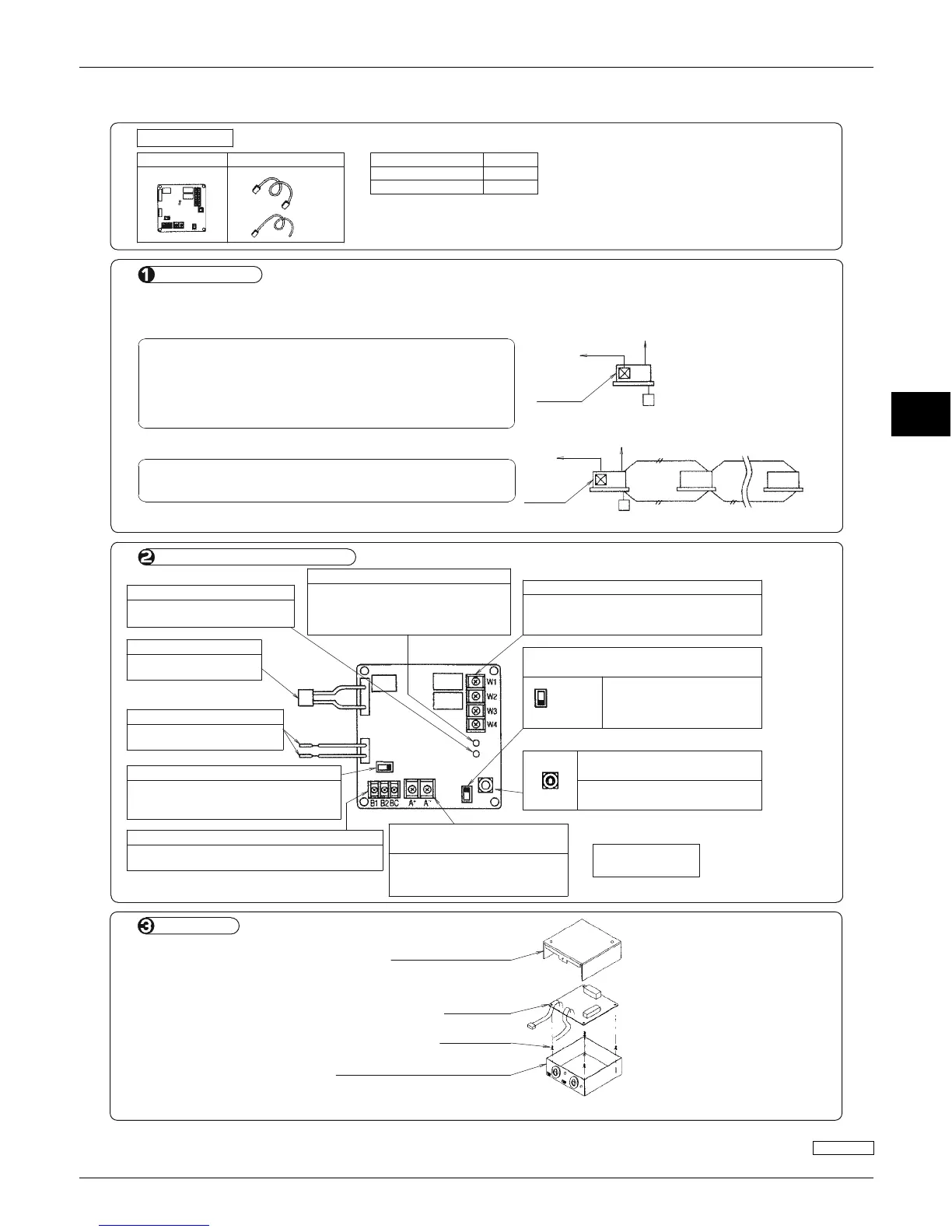
Names of parts and function
System outline
Terminal board for display signal (X3M)
1. Individual control (Each indoor unit is controlled individually.)
(2)
Indoor unit
BRC1E71 ×8 kits
Note) Connector No. X35A
KRP4A74 ×8 kits
×3
Adaptor
2. Group control (Multiple indoor units are controlled as a group.)
This system requires the following parts.
Remote control input terminal board (X1M)
Remote controller
Power supply connector
To outdoor unit
Changeover switch (SS1) (Factory set: Volt)
×1
Accessories
Check if the following accessories are included in the kit.
Relay harness
(1)
×1 each
Remote controller
Indoor unit max. 16 units
This system requires the following parts.
PCB support
Installation manual
To outdoor unit
×4
•
Adaptor........................................................................KRP4A74
•
Remote controller (For operation control)....................BRC1E71
•
Adaptor........................................................................ KRP4A74
•
Remote controller (For operation control)....................BRC1E71
Lid of installation box
PCB support
Installation box for adaptor PCB
Adaptor
(KRP4A74)
KRP1BA101 (Optional accessory)
Installation
This kit enables remote control (ON/OFF control, temperature setting, operation display, error display) and can be used with the
following systems though it cannot be used in conjunction with other optional controllers for centralized control.
This lamp flashes while the
CPU is operating normally.
To connector on indoor
unit PCB.
To P1 and P2 on indoor
unit terminal board.
Connects control input from the remote control
(Central control monitor, timer, etc.).
Set to "Non volt" to input a no-voltage
normally open contactor on the remote
control input terminal board (TeS1).
This lamp lights up when trouble
occurs in electrical wiring or setting
switches. Remote control is disabled.
(This LED is out in constant operation.)
Connects operation and error output to a
remote point (Central control monitor, etc.).
(Normal operation: W1, W2; Error: W3, W4)
Temperature setting ON/OFF switch (SS2)
(Factory set: Possible)
Do not change to "Impossible".
Otherwise, temperature setting
by the remote control cannot be
made.
Impossible
Possible
Control mode selector switch (RS1)
(Factory set: 0)
For selecting the type of system
operation permitted via remote.
This function cannot be used for
this kit. Never apply voltage to
this for any reason whatsoever.
Temperature setting input
terminal (X2M)
For details, see
the electric wiring.
To central
control monitor
KRP1BA101
(Optional accessory)
Note: Installation box for adaptor PCB is required to install the adaptor.
To central
control monitor
1P161220-1A
 Loading...