Check SiUS121736EA
211 Service Diagnosis
8.3 Hall IC Check
Check No.04 CDXS, FDXS Series
1. Check the connector connection.
2. With the power on, operation off, and the connector connected, check the following.
(1) Output voltage of about 5 V between pins 1 and 3.
(2) Generation of 3 pulses between pins 2 and 3 when the indoor fan motor is operating.
If NG in step (1) Æ Defective PCB Æ Replace the PCB (control PCB).
If NG in step (2) Æ Defective Hall IC Æ Replace the indoor fan motor.
If OK in both steps (1) and (2) Æ Replace the PCB (control PCB).
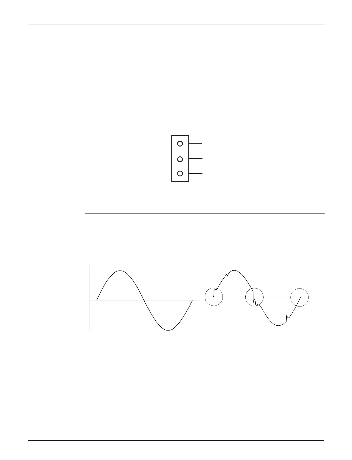
8.4 Power Supply Waveform Check
Check No.11 Measure the power supply waveform between No. 1 and No. 2 on the terminal board, and check
the waveform disturbance.
Check if the power supply waveform is a sine wave (Fig.1).
Check if there is waveform disturbance near the zero-cross (sections circled in Fig.2)
1
Gray (power supply)
Purple (signals)
Blue (grounding)
2
3
(R14211)
S7
[Fig.1] [Fig.2]
(R1736)
(R1444)
 Loading...