39
Maintenance
Troubleshooting
When an alarm is activated
An alarm is generated when a defect that disables the continuance of operation is generated in OILCON.
To cancel the alarm, turn OFF the power supply, and then turn it ON again.
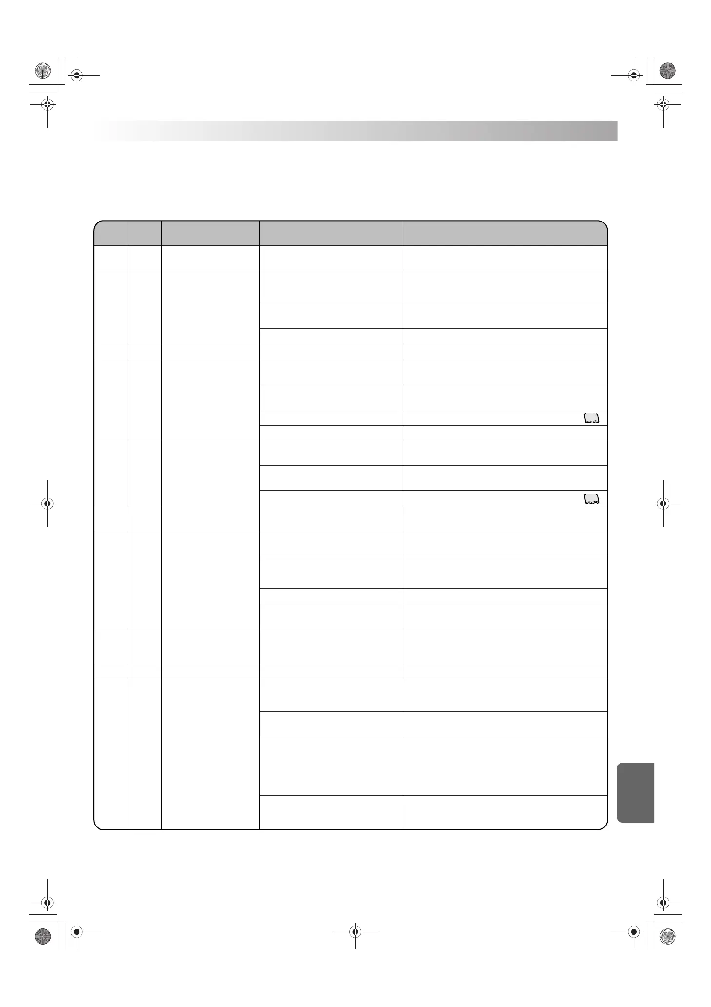
Alarm list
Alarm
code
Alarm∗
level
Description Cause Corrective action
Heater overheat (S4B1:S184)
(-H model only)
DC fan motor lock error
High pressure error
Compressor high temperature
error
Compressor (M2C) lock
System error
∗Alarm level 1: Compressor, pump and fan stop.
Alarm level 2: Only compressor stops.
Pump over-current relay
(K1S:S182) is activated.
AKZ149, 329, 439: 2.5A
Optional protection device is
activated. (OP.)
Pump outlet oil temperature error (Th10)
Inlet oil temperature is higher
than 60˚C.
AA 2
A6 2
E1 1
E3 2
E5 2
E6 2
EH 1
EJ 1 or 2
FE 1
FH 2
1) AKZ type:
No oil flow
1) Internal parameter setting is invalid.
3)
The air filter is clogged, or the condenser is dirty.
4) Any factor other than the above
3)
The air filter is clogged, or the condenser is dirty.
3)
The pump motor wiring has a break. (Open-phase)
1)
The pump outlet oil temperature is higher than 65˚C.
1) The oil temperature or room temperature
is higher than the specified range.
2) There is an obstacle near the air
intake/exhaust port.
1) The oil temperature or room temperature
is higher than the specified range.
2)
There is an obstacle near the air intake/
exhaust port.
1) Fault of the compressor
(Replace the compressor.)
1)
The pump is overloaded with high-viscosity
oil.
4) A foreign object is caught in the pump, or
the pump motor has a fault.
2)
There is an obstacle near the air intake/exhaust
port, resulting in cooling capacity deterioration.
2) Because the power supply voltage falls
below the operating range, the pump
current has increased.
1)
The optionally-connected protection device
(or factory-connected device, if it is
incorporated in the unit) has been activated.
1)
The heating value of the main machine has
exceeded the cooling capacity of the Oil
Cooling Unit. (Improper model selection)
Check if the oil circuit is properly connected and the pump
normally operates.
3) Fault of the DC fan motor Replace the DC fan motor.
Do not place any object that blocks ventilation at 500 mm or
shorter distance from the air intake/exhaust port.
Do not place any object that blocks ventilation at 500 mm or
shorter distance from the air intake/exhaust port.
Check if the power supply voltage is not lower than the
specified operating range. Check for an instantaneous power
supply voltage drop at startup of peripheral equipment.
If the unit is properly installed and the compressor runs at
100% capacity (capacity setting can be checked in the monitor
mode), select a model that provides larger cooling capacity.
Do not place any object that blocks ventilation at 500 mm or
shorter distance from the air intake/exhaust port.
Use an operating fluid that provides 1.4 to 200 mm
2
/s viscosity
in the specified oil temperature range.
Check the condition detected with the relevant protection device.
Check if the oil piping system is not blocked (fully closed).
Clean the air filter. (See “Maintenance/Inspection” on page .)
2) Fan motor-control board communication
error
1) Rotation speed of fan motor is insufficient
because of drop of DC voltage by break-
ing wire or looseness of connector.
Check the connector insertion and wire break.
Replace the control board.
Check the insertion and breaking of the signal wire and engine
wire between the filter board and the inverter board.
Replace the control board.
Use the unit within the specified operating range.
Contact DAIKIN Contact Center.
Use the unit within the specified operating range.
Replace the compressor.
Replace the pump motor.
Replace the pump motor.
37
Clean the air filter. (See “Maintenance/Inspection” on page .)
37
3)
The unit is running under capacity
suppressing control, because the standard
temperature (room temperature: 35˚C, oil
temperature: 35˚C) has been exceeded.
If the standard temperature is exceeded, the cooling capacity
becomes smaller than the nominal capacity, because the unit
runs under capacity suppressing control.
Make sure that the cooling capacity of the Oil Cooling Unit is
larger than the main machine heating value throughout the oper-
ating temperature range.
4) Temperature control is disabled because
the unit is operated in Mode 9 (capacity
direct designation mode).
Select an appropriate operation mode.
(The capacity direct designation mode does not execute temper-
ature feedback control.)
PIM00318A_EN.fm Page 39 Tuesday, October 26, 2010 12:37 PM
 Loading...