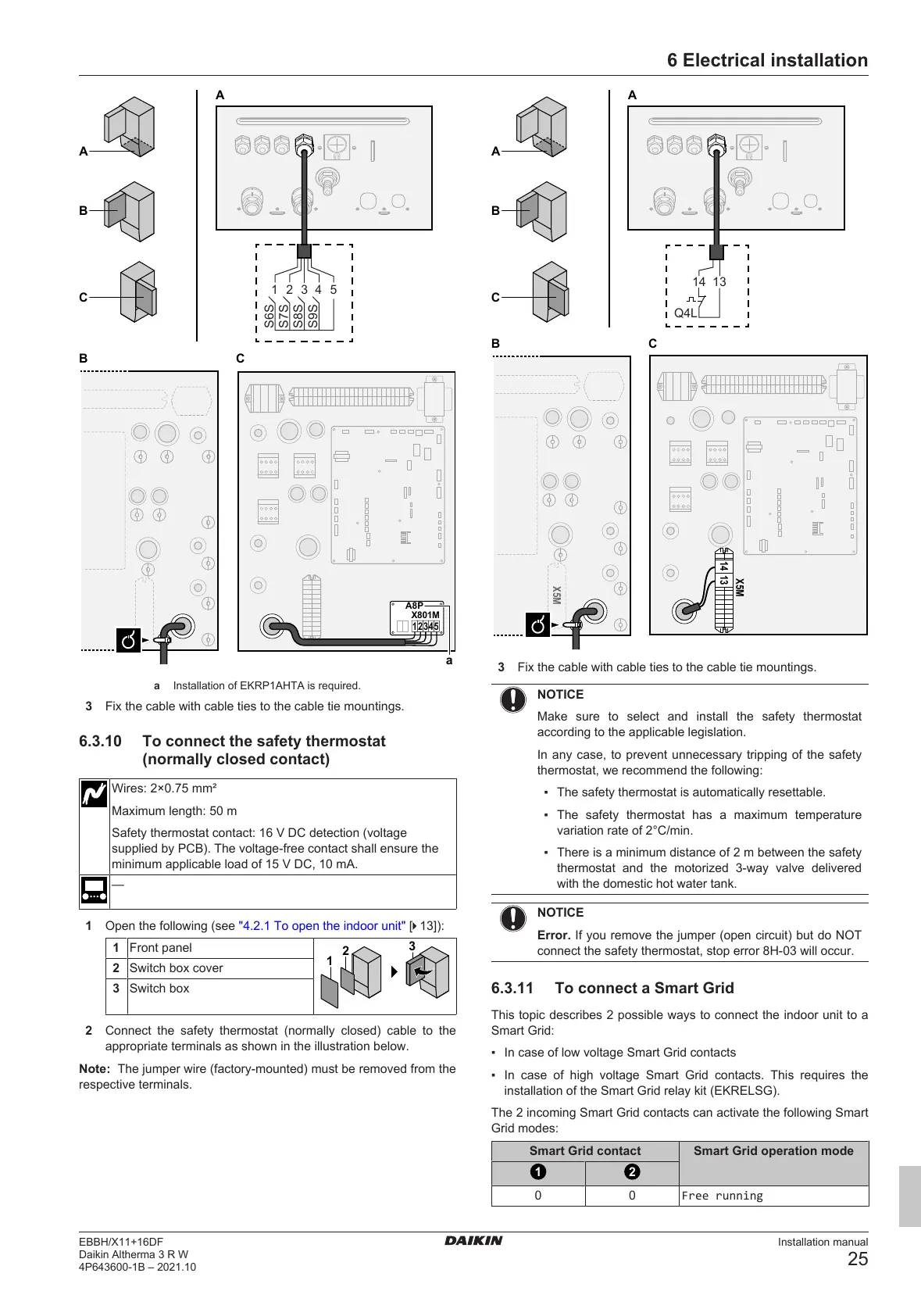
a Installation of EKRP1AHTA is required.
3 Fix the cable with cable ties to the cable tie mountings.
6.3.10 To connect the safety thermostat
(normally closed contact)
Wires: 2×0.75mm²
Maximum length: 50m
Safety thermostat contact: 16VDC detection (voltage
supplied by PCB). The voltage-free contact shall ensure the
minimum applicable load of 15VDC, 10mA.
—
1 Open the following (see "4.2.1To open the indoor unit"[413]):
1 Front panel
2 Switch box cover
3 Switch box
2 Connect the safety thermostat (normally closed) cable to the
appropriate terminals as shown in the illustration below.
Note: The jumper wire (factory-mounted) must be removed from the
respective terminals.
3 Fix the cable with cable ties to the cable tie mountings.
NOTICE
Make sure to select and install the safety thermostat
according to the applicable legislation.
In any case, to prevent unnecessary tripping of the safety
thermostat, we recommend the following:
▪ The safety thermostat is automatically resettable.
▪ The safety thermostat has a maximum temperature
variation rate of 2°C/min.
▪ There is a minimum distance of 2m between the safety
thermostat and the motorized 3‑way valve delivered
with the domestic hot water tank.
NOTICE
Error. If you remove the jumper (open circuit) but do NOT
connect the safety thermostat, stop error 8H-03 will occur.
6.3.11 To connect a Smart Grid
This topic describes 2 possible ways to connect the indoor unit to a
Smart Grid:
▪ In case of low voltage Smart Grid contacts
▪ In case of high voltage Smart Grid contacts. This requires the
installation of the Smart Grid relay kit (EKRELSG).
The 2 incoming Smart Grid contacts can activate the following Smart
Grid modes:
Smart Grid contact Smart Grid operation mode
 Loading...