10 Technical data
Installation manual
40
EBBH/X11+16DF
Daikin Altherma 3 R W
4P643600-1B – 2021.10
10 Technical data
A subset of the latest technical data is available on the regional Daikin website (publicly accessible). The full set of latest technical data is
available on the Daikin Business Portal (authentication required).
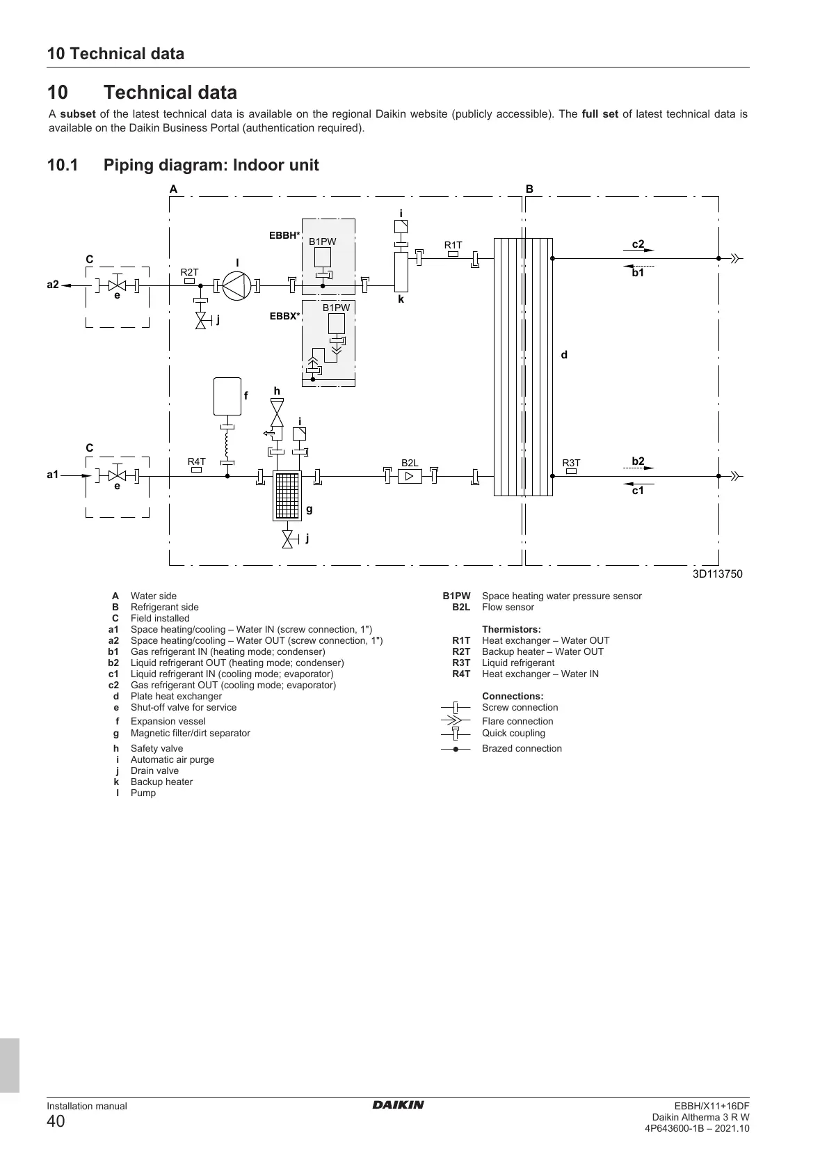
10.1 Piping diagram: Indoor unit
A Water side B1PW Space heating water pressure sensor
B Refrigerant side B2L Flow sensor
C Field installed
a1 Space heating/cooling – Water IN (screw connection, 1") Thermistors:
a2 Space heating/cooling – Water OUT (screw connection, 1") R1T Heat exchanger – Water OUT
b1 Gas refrigerant IN (heating mode; condenser) R2T Backup heater – Water OUT
b2 Liquid refrigerant OUT (heating mode; condenser) R3T Liquid refrigerant
c1 Liquid refrigerant IN (cooling mode; evaporator) R4T Heat exchanger – Water IN
c2 Gas refrigerant OUT (cooling mode; evaporator)
d Plate heat exchanger Connections:
e Shut-off valve for service Screw connection
f Expansion vessel Flare connection
g Magnetic filter/dirt separator Quick coupling
h Safety valve Brazed connection
i Automatic air purge
j Drain valve
k Backup heater
l Pump
 Loading...