48
3 Wire
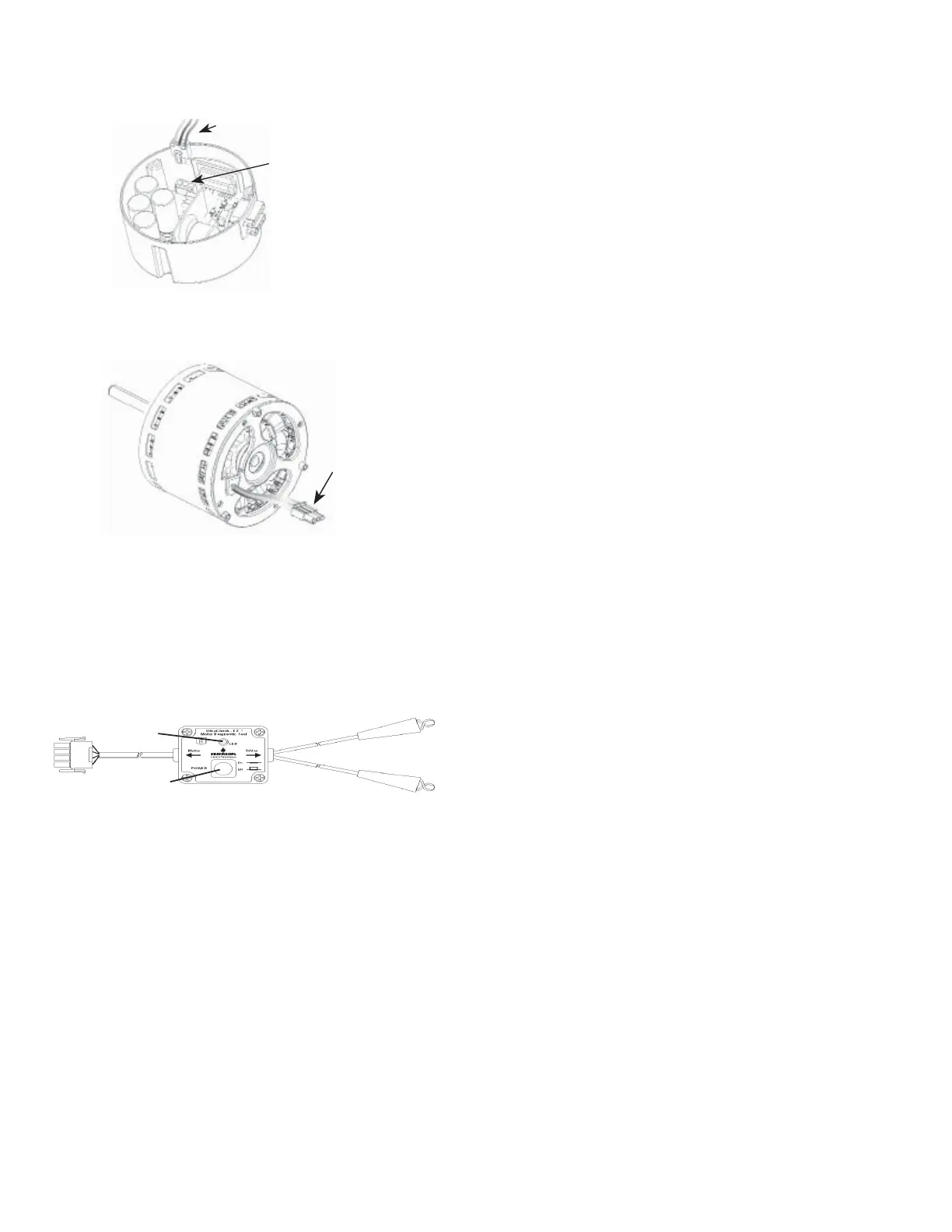
Motor-to-Control Harness
3 Pin Connector
Motor
Connector
Beyond basic visual checks and voltage / resistance checks;
the Emerson ECM motor may be tested with an Emerson
UltraCheck-EZ™ diagnostic tool (Part UTT-01). This tool
will test the motor windings and also the communicating
module of the motor.
USING THE EMERSON
®
ULTRACHECK-EZ™ DIAGNOSTIC TOOL
Orange Power Button
Green LED
Emerson
®
Ultracheck-EZ™ Diagnostic Tool
• Turn off power to the furnace being serviced and verify
with a volt meter
• Disconnect the 4 wire communication cable from the
motor control unit (end bell)
• Connect the 4 wire connector of the diagnostic tool
to the end bell communicating connector
• Attach one of the alligator clips of the diagnostic tool
to the 24 volt hot terminal of the furnace transformer
and the other alligator clip to the 24 volt common
(ground) terminal. The alligator clips are not polarity
sensitive
• Turn ON furnace power.
SERVICE & OPERATION
• The orange button of the diagnostic tool sends a sig-
nal to the UltraTech
®
motor to rotate when pressed.
There may be a five second delay between the time
the button is pressed and the motor begins to rotate.
If the orange button does not illuminate when pressed,
the tool is not connected to a 24 volt supply or it is
defective. The GREEN LED is an indicating signal that
communication is taking place. If the green LED does
not blink, the end bell should be replaced.
 Loading...


