SERVICING
57
S-305 CHECKING MAIN BURNERS
The main burners are used to provide complete combus-
tion of various fuels in a limited space, and transfer this
heat of the burning process to the heat exchanger.
Proper ignition, combustion, and extinction are primarily
due to burner design, orifice sizing, gas pressure, pri-
mary and secondary air, vent and proper seating of burn-
ers.
Depending on the size of the furnace, each furnace will
havefrom three to six inshot burners. Burners are pre-
cisely constructed of aluminized steel and designed to pro-
vide proper ignition and flame stability. When converting
a modulating furnace to L.P. gas, the factory installed burn-
ers must be replaced by burners that come in the L.P. kit.
WARNING
D
ISCONNECT
ALL
G
AS AND
E
LECTRICAL
P
OWER
S
UPPLY.
In checking main burners, look for signs of rust, oversized
and undersized carry over ports restricted with foreign
material, etc, refer to Beckett Burner drawing.
Beckett Burner
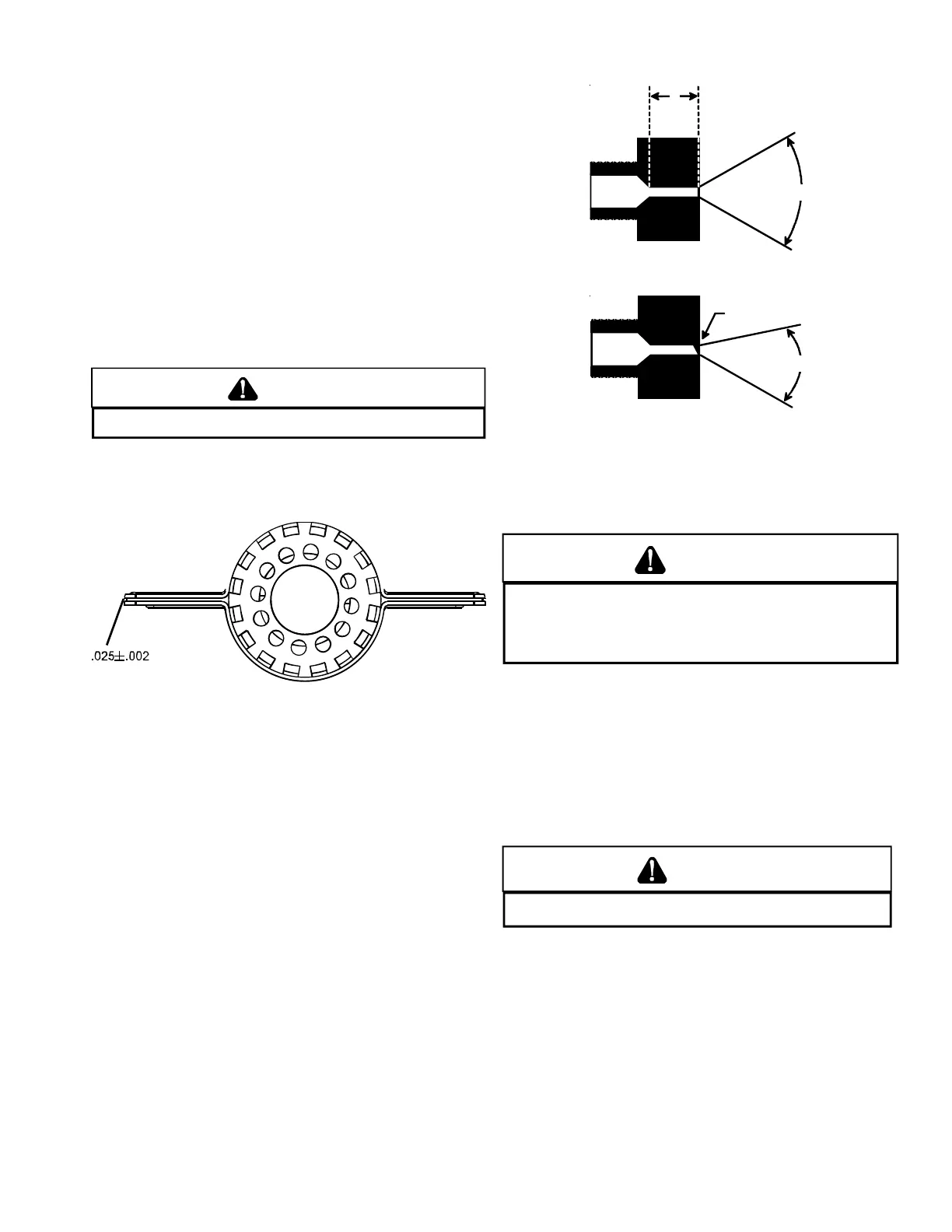
S-306 CHECKING ORIFICES
A fixed gas orifice is used in all Daikin furnaces. That is
an orifice which has a fixed bore and position as shown in
the following drawing.
No resizing should be attempted until all factors are taken
into consideration such as inlet and manifold gas pres-
sure, alignment, and positioning, specific gravity and BTU
content of the gas being consumed.
Orifices should be treated with care in order to prevent
damage. They should be removed and installed with a box-
end wrench in order to prevent distortion. In no instance
should an orifice be peened over and redrilled.
A
GAS
STREAM
B
The length of Dimension "A" determines the angle of Gas
Stream "B".
DENT OR
BURR
GAS
STREAM
B
A dent or burr will cause a severe deflection of the gas
stream.
S-307 CHECKING GAS PRESSURE
Gas Supply Pressure Measurement
T
O PREVENT UNRELIABLE OPERATION OR EQUIPMENT DAMAGE, THE
INLET GAS SUPPLY PRESSURE MUST BE AS SPECIFIED ON THE UNIT
RATING PLATE WITH ALL OTHER HOUSEHOLD GAS FIRED APPLIANCES
OPERATING.
CAUTION
Gas inlet and manifold pressures should be checked in ac-
cordance to the type of fuel being consumed.
The line pressure supplied to the gas valve must be within
the range specified below. The supply pressure can be mea-
sured at the gas valve inlet pressure tap or at a hose fit-
ting installed in the gas piping drip leg. The supply pres-
sure must be measured with the burners operating. To mea-
sure the gas supply pressure, use the following procedure.
WARNING
D
ISCONNECT ELECTRICAL POWER AND SHUT OFF GAS SUPPLY.
1. After turning off gas to furnace at the manual gas shut-
off valve external to the furnace, remove burner com-
partment door to gain access to the gas valve.
2. Connect a calibrated water manometer (or appropriate
gas pressure gauge) at either the gas valve inlet pres-
sure tap or the gas piping drip leg as shown in the fol-
lowing figures.
 Loading...


