PRODUCT DESIGN
34
34
Add 5% OFF OFF
Minus 5% ON OFF
Add 10% OFF ON
Minus10% ON ON
Trim Amount
SWITCH
S3
DISABLE OFF
ENABLE ON
SWITCH 2
Trim Enable
S5
AIR FLOW DATA
NOTE: Airflow data shown applies to non-communicating mode operation only. For a fully communicating system, please
see the outdoor unit’s installation instructions for cooling and pump heating airflow data.
See ComfortNet™ System - Airflow Consideration section for details.
TAP S3-1S3-2S3-3S3-4S4-1S4-2S4-3S4-4
A OFF OFF OFF OFF OFF OFF OFF OFF
B ON OFF On OFF On OFF On OFF
C OFF ON OFF ON OFF ON OFF ON
D ONONONONONONONON
Profiles
A
B
C
D
Speed Selection Dip Switches
Heat
Selection
Switches
Pre-Run Short-Run OFF Delay
Cool
Selection
Switches
Adjust
Selection
Switches
Profile
Selection
Switches
------------
------------
------------
------------------
To Set Ai rflow: (1) Sel ect mo del and desir ed Hi gh Stag e Cooli ng Airfl ow. D etermi ne the
corre spon di ng tap (A, B, C, or D). Se t dip swi tch es S3-1* a nd S3 -2* to the approp riate ON/OFF
position s. (2) Se lect mode l an d desi red High Stage Heatin g Airflow. Determin e the
corre spon di ng tap (A, B, C, or D). Se t dip swi tch es S4-3* a nd S4 -4* to the approp riate ON/OFF
position s. (3) Se lecting Air flow Adju stme nt Factor: For 0% trim set S5-2* to OFF (trim disa bl ed).
If trim is desi red se t S5-2* to ON (trim en abl ed ) a nd set S3-3 * and S3 -4* to ap prop riate ON/OFF
position s. Tap A is +5%, Ta p B i s -5%, Tap C is +10%, Tap D is -1 0%.
To Set C omfort Mo de: Select D esire d Comfort Mode p rofile (see p rofiles ab ove). Set d ip
switches S4-1* and S4-2 * to the approp riate ON/OFF posi tion s.
Dehumid ifica tion: To en able, se t swi tch S5-1* to ON. C oo ling ai rflow will b e redu ced to 85% of
nomi na l valu e during cool ca ll . To di sabl e, set sw itch S5-1* to OFF.
Continuous Fan Sp eed : Set di p switche s S5 -3* a nd S5-4 * to sele ct one of 4 continuous fan
spe eds (25 %, 5 0%, 75 %, or 1 00%). "Se e insta lla tion manua l for detai ls."
*the "S" n umber refers to on e of four la bel ed dip switch se ction s,
each contai ni ng 4 indi vid ual d ip sw itches.
The following number refers to the individual labeled dip switch within that section.
60 sec/100%
60 sec/100%
60 sec/100%
30 sec/50%30 sec/50%
30 sec/50%
7.5 min/82%
7.5 min/82%
0140F01786
Model TAP
Low
St age
Coo l
High
Stage
Cool
Low
St age
Heat
High
Stage
Heat
DD80VC0603B***
A
B
C
D
390
520
650
78
600
800
1000
1200
735
805
875
94
1050
1150
1250
1350
DD80VC0805C***
A
B
C
D
520
715
910
117
800
1100
1400
1800
945
1015
1085
1155
1350
1450
1550
1650
DD80VC1005C***
A
B
C
D
553
748
943
120
850
1150
1450
1850
1085
1115
1225
1260
1550
1650
1750
1800
DM80VC0604B***
A
B
C
D
390
520
715
910
600
800
1100
1400
875
945
1015
1085
1250
1350
1450
1550
DM80VC0805C***
A
B
C
D
520
715
910
117
800
1100
1400
1800
1050
1120
1190
1260
1500
1600
1700
1800
DM80VC1005C***
A
B
C
D
520
715
910
117
800
1100
1400
1800
1210
1225
1245
1260
1725
1750
1775
1800
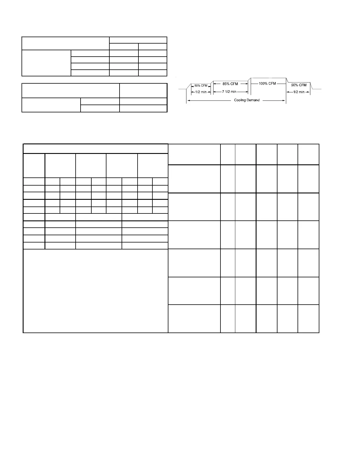
• Profile D ramps up to 50% of the demand for 1/2
minute, then ramps to 85% of the full cooling demand
airflow and operates there for approximately 7 1/2 min-
utes. The motor then steps up to the full demand air-
flow. Profile D has a 1/2 minute at 50% airflow OFF
delay.
OFF
OFF
 Loading...


