SERVICING
75
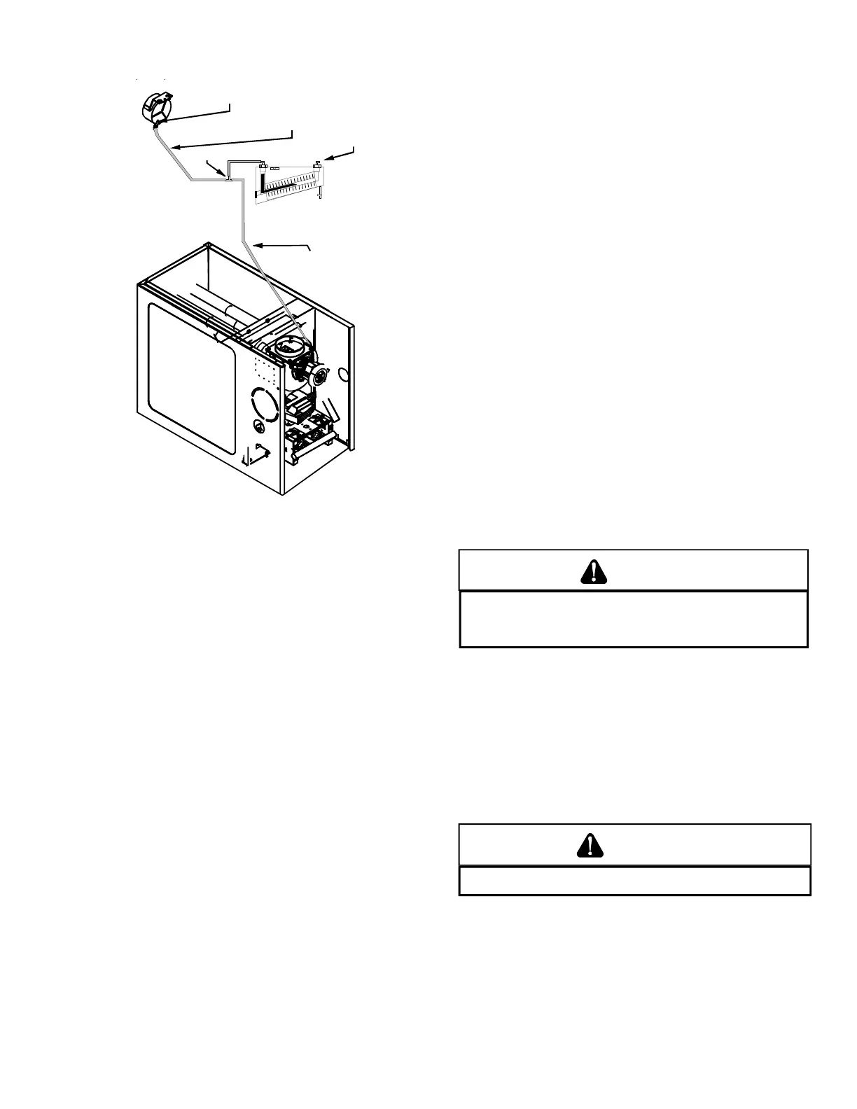
Induced Draft Blower
Pressure Switch
Pressure Switch
Hose
1/4" Tee
Hose to Induced
Draft Blower Tap
Inclined Manometer
S-311 HIGH ALTITUDE APPLICATION (USA)
The furnace as shipped requires no change to run between
0 - 4500 feet. Do not attempt to increase the firing rate by
changing orifices or increasing the manifold pressure below
4500 feet. This can causepoor combustion and equipment
failure. High altitude installations above 4500 feet may re-
quire both a pressure switch and an orifice change. These
changes are necessary to compensate for the natural re-
duction in the density of both the gasfuel and the combus-
tion air at higher altitude.
For installations above 4500 feet, please refer to your dis-
tributor for required kit(s). Contact the distributor for a tabu-
lar listing of appropriate manufacturer’s kits for propane gas
and/or high altitude installations. The indicated kits must
be used to insure safe and proper furnace operation. All
conversions must be performed by a qualified installer, or
service agency.
In some areas the gas supplier may artificially derate the
gas in an effort to compensate for the effects of altitude. If
the gas is artificially derated the appropriate orfice size must
be determined based on the BTU/ft
3
content of the derated
gas and the altitude. Refer to the National Fuel Gas Code,
NFPA 54/ANSI Z223.1, and information provided by the gas
supplier to determine the proper orifice size.
S-312 CHECKING FOR DELAYED IGNITION
Delayed ignition is a delay in lighting a combustible mix-
ture of gas and air which has accumulated in the combus-
tion chamber.
When the mixture does ignite, it may explode and/or rollout
causing burning in the burner venturi.
If delayed ignition should occur, the following should be
checked:
1. Improper gas pressure - adjust to proper pressure (See
S-307 CHECKING GAS PRESSURE).
2. Improper burner positioning - burners should be in lo-
cating slots, level front to rear and left to right.
3. Carry over (lighter tube or cross lighter) obstructed -
clean.
4. Main burner orifice(s) deformed, or out of alignment to
burner - replace.
S-313 CHECKING INTEGRATED IGNITION
CONTROL BOARDS
This section discusses various integrated ignition boards
used on models listed in this manual. You will be guided
though some common diagnostic procedures.
NOTE: Failure to earth ground the furnace, reversing the
neutral and hot wire connection to the line (polarity), or a
high resistance connection in the neutral line may cause
the control to lockout due to failure to sense flame.
T
O AVOID THE RISK OF ELECTRICAL SHOCK, WIRING TO THE UNIT
MUST BE PROPERLY POLARIZED AND GROUNDED.
D
ISCONNECT POWER
BEFORE PERFORMING SERVICE LISTED BELOW.
WARNING
The ground wire must run from the furnace all the way back
to the electrical panel. Proper grounding can be confirmed
by disconnecting the electrical power and measuring re-
sistance between the neutral (white) connection and the
burner closest to the flame sensor. Resistance should be
less than 10 ohms.
The ignition control is a combination electronic and elec-
tromechanical device and is not field repairable. Complete
unit must be replaced.
L
INE VOLTAGE NOW PRESENT
WARNING
These tests must be completed within a given time frame
due to the operation of the ignition control.
The ignition control is capable of diagnosing many furnace
failures to help in troubleshooting. A flashing red or green
diagnostic indicator light on the control flashes a code for
any detected failures. The control utilizes a dual, 7-seg-
ment LED display to indicate diagnostic codes.
 Loading...


