76
SERVICING
When the control is powered up normally the light will be on
continuously. The display wil indicate "ON" when pow-
ered and in standby mode. This can be used to test for 120
volts and 24 volts to the control since both must be present
for the light to be on. If this step fails, check for 120 volts to
the control and check the transformer and its associated
wiring. If this step is successful give the control a call for
heat and wait five (5) seconds or until the furnace goes into
lockout. If the control detects a failure it will now be shown
on the diagnostic indicator light/display. Refer to the Ab-
normal Operation section in the Sequence of Operation sec-
tion of this manual for more detail on failure codes.
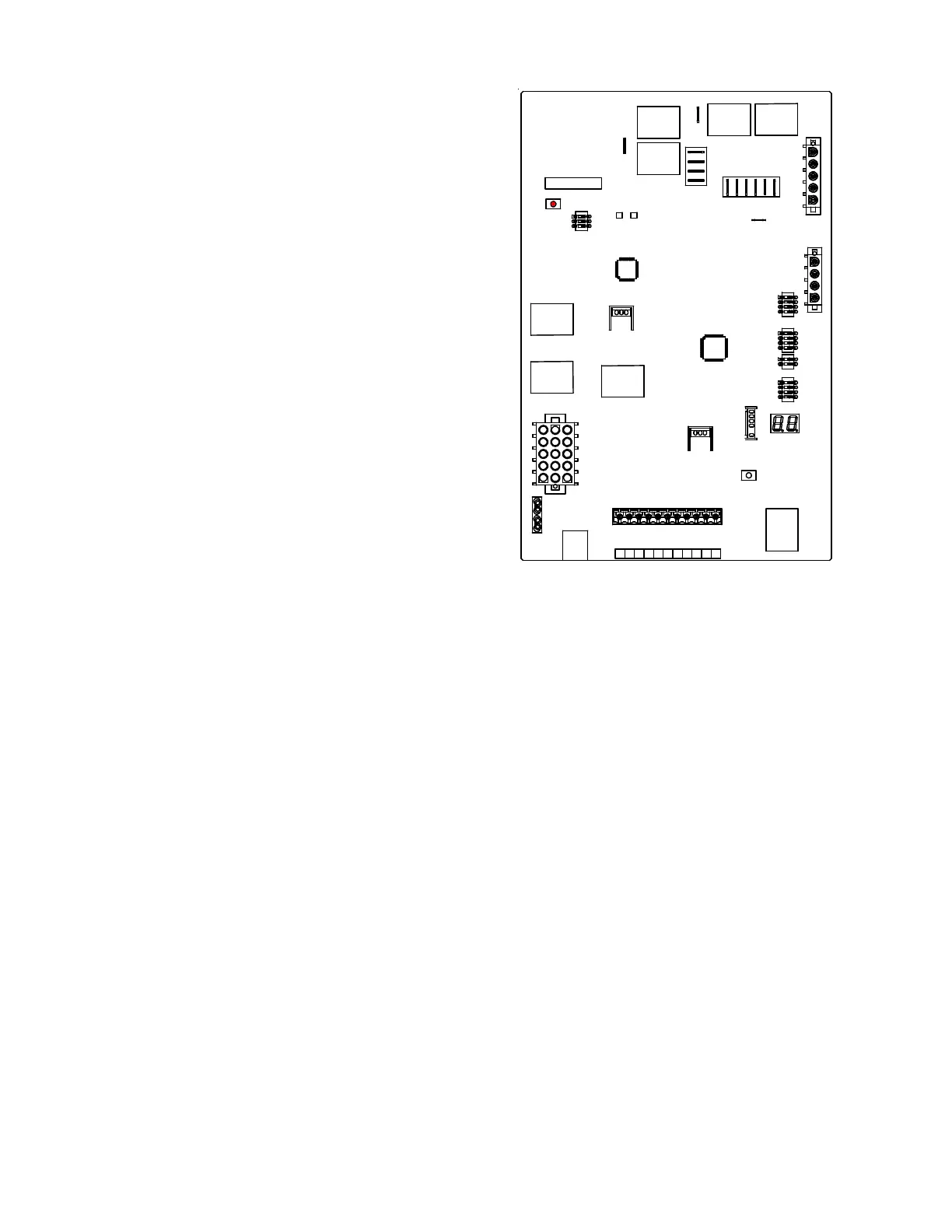
PCBKF103 / PCBKF104 / PCBKF105
1. Check for 120 volts from Line 1 (Hot) to Line 2 (Neutral)
at the ignition control. No voltage, check the door switch
connections and wire harness for continuity.
2. Check for 24 volts from W1 to C terminal on the ignition
control. No voltage. Check transformer, room thermo-
stat, and wiring.
If you have 24 volts coming off the transformer but re-
ceive approximately 13 volts on the terminal board be-
tween (C) and (R), check for blown fuse.
3. Check for 120 volts to the induced draft blower (low-
stage) by measuring voltage between Pin 3 and Pin 4
(on the 5-pin connector) located on circuit board. No
voltage, check for loose connection in the 5-pin con-
nector or replace ignition control.
Check for 120 volts to the induced draft blower (high-
stage) by measuring voltage between Pin 2 and Pin 4
(on the 5-pin connector) located on circuit board. No
voltage, check for loose connection in the 5-pin con-
nector, no call for high stage heat or replace ignition
control.
2 Y2
HUM
OG Y1C
W1
R
DE
W2
1
4. If voltage is present in Steps 1 through 3 and the in-
duced draft blower is operating, check for 120 volts to
the ignitor during the preheat cycle. Measure voltage
between Pin 1 and Pin 5 (on the 5-pin connector) lo-
cated on ignition control. No voltage, check low stage
and high stage pressure switches or replace the igni-
tion control board.
5. After the ignitor warmup time, begin checking for 24
volts to the gas valve. Voltage will be present for seven
seconds only if proof of flame has been established.
6. If proof of flame was established voltage will be provided
to the air circulation blower following the heat on delay
period.
a. BEFORE replacing the ECM motor assembly or the
end bell, first check the motor with an Emerson
UltraCheck-EZ
TM
diaganostic tool . If the motor runs
with the diagnostic tool, the motor is good. To check
the end bell, see the previous variable speed testing
section of this manual before replacing the end bell.
b. The two-stage variable speed furnaces should have
120 Volts at the motor at all times, even without a
call for cooling or heating. These motors receive their
operational signals (5 Volts dc) through the 4-pin wir-
ing harness, connected between the motor and inte-
grated control board. NOTE: For complete trouble-
shooting information on units using the ECM blower
motors, refer to the servicing section - Checking Air
Circulator Blowers (S-16B) in this service manual.
 Loading...


