 Loading...
Do you have a question about the Daikin Emura 3 Series and is the answer not in the manual?
| Refrigerant | R32 |
|---|---|
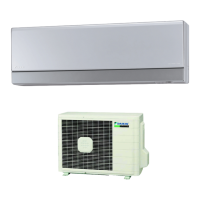
| Sound Pressure Level (Indoor Unit) | 19 dB - 42 dB |
| Noise Level (Indoor Unit) | 19 dB - 42 dB |
| Features | Eco-friendly refrigerant |
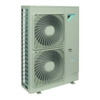
| Outdoor Unit Dimensions (H x W x D) | 550 mm x 780 mm x 285 mm |
| Outdoor Unit Weight | 32 kg |
| Power Supply | 220-240 V, 50 Hz |
| Energy Efficiency Class (Cooling) | Up to A+++ (depending on model) |
| Energy Efficiency Class (Heating) | Up to A+++ (depending on model) |