3 CONTROL SYSTEM DESCRIPTION
3.1 Architecture
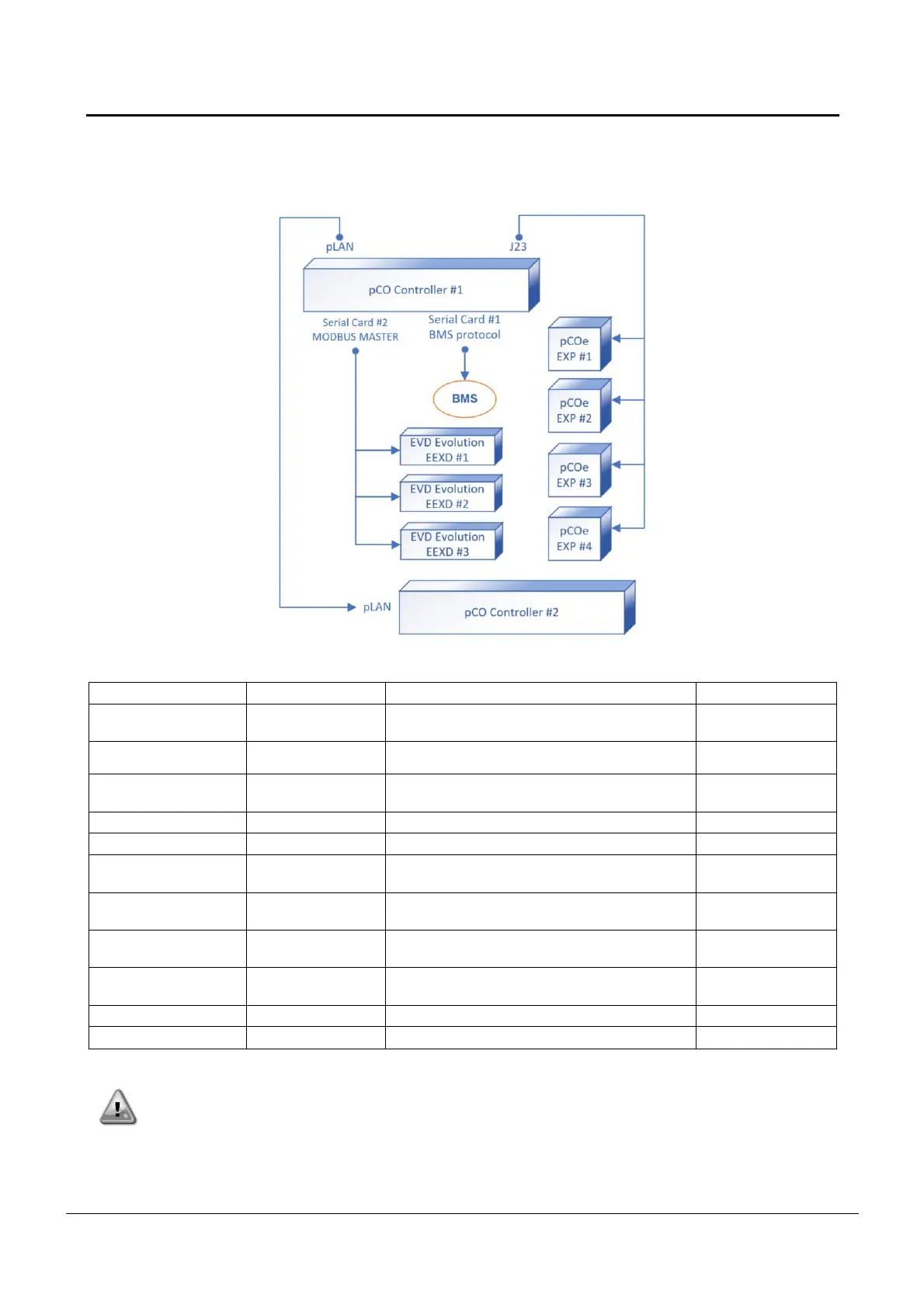
The overall control system architecture is described in the following picture:
pCO5+ “Large”
Built In display (*)
Unit control
Compressors #1 & #2 control
Yes on 3
compressors units
Additional hardware for compressors #1 & 2 or
for compressors #3
Heat recovery or Heat pump control
Additional fan steps for compressors #1 & #2 or
for compressors #3
Electronic expansion valve control for
compressor #1
Electronic expansion valve control for
compressor #2
Electronic expansion valve control for
compressor #3
Yes on 3
compressors units
Special characters or additional display
(*) The contemporaneous presence of built-in display and additional PGD may be accepted.
CAUTION: Maintain the correct polarity when connecting the power supply to the boards, otherwise
the peripheral bus communication will not operate and the boards may be damaged.
 Loading...