10.6.7 Bad Leaving Water Temperature Reset Input
This alarm is generated when the Setpoint Reset option has been enabled and the input to the controller is out of the
admitted range.
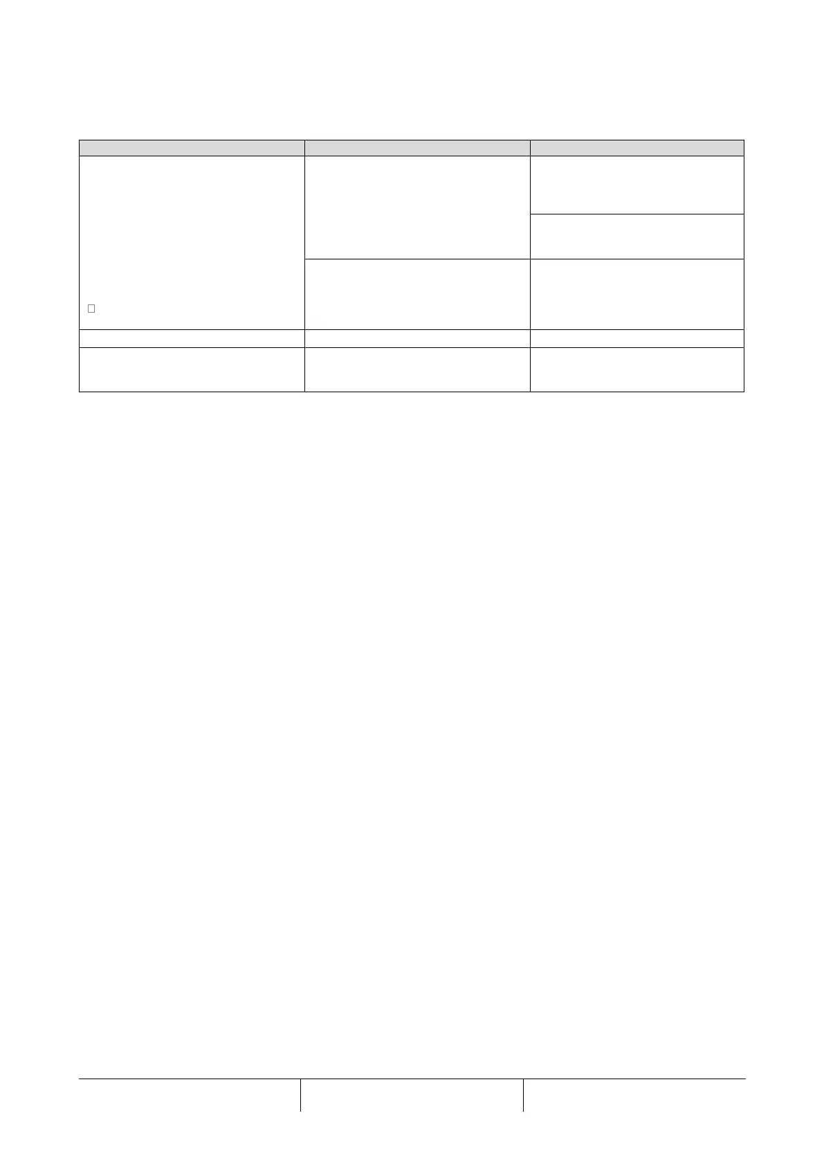
Unit status is Run.
Bell icon is moving on controller’s
display. LWT Reset function cannot
be used.
String in the alarm list:
BadSetPtOverrideInput
String in the alarm log:
BadSetPtOverrideInput
String in the alarm snapshot
BadSetPtOverrideInput
LWT reset input signal is out of range.
For this warning out of range is a
signal less than 3mA or more than
21mA.
Check for values of input signal to
the unit controller. It has to be in the
allowed mA range.
Check for electrical shielding of
wirings.
Check for right value of the unit’s
controller output in case input signal
is into allowed range.
Automatically clears when the signal
returns in the allowed range.
10.7 Circuit Alarms
All circuit stop alarms require shutdown of the circuit on which they occur. Rapid stop alarms do not do a pumpdown
before shutting off. All other alarms will do a pumpdown.
When one or more circuit alarms are active and no unit alarms are active, the alarm output will be switched on and off on
5 second intervals.
Alarm descriptions apply to all circuits, the circuit number is represented by ‘N’ in the description.

 Loading...


