OM 1239 14 www.DaikinApplied.com
• The fault terminal (A) energizes while the unit is
in defrost mode. It will stay energized until the
temperature recovers to 36°F for standard equipment
(14.5°F for extended range). A to C will be used to
indicate an alarm signal. The previous operation of
heating or cooling determines how the low suction
temp alarm must be reset. The fan and pump remain
available for operation.
■ Cooling mode
When the suction line temperature falls below 28°F standard
equipment (28°F extended range) in cool mode the:
• Compressor de-energizes.
• The fan and pump remain available for operation.
• Alarm output energizes.
• When the suction line temperature recovers to 36°F
standard equipment (14.5°F on extended range) the
low temperature fault continues and the compressor
will be locked out.
■ Fan only mode
When the suction line temperature falls below 28°F standard
equipment (28°F extended range) in cool mode the:
• The fan and pump remain available for operation.
• Alarm output energizes.
The previous operation of heating or cooling determines
how the low suction temp alarm must be reset.
• Interstaging timer – A default value of 5 minutes
between staging of compressors, this feature
minimizes short cycling of compressors and
improves comfort.
• Motorized water valve or pump start – When
there is a call for cooling, dehumidication or
heating, the MicroTech III unit controller will energize
its IV/PR (H8) terminal to open the motorized water
valve or start the loop pump 45 seconds prior to
starting the compressor. The IV/ PR (H8) terminal
may be “daisy chained” between 200 units.
• Lead compressor fail replacement – Upon
detection of a lead compressor fault and the
lag compressor is available, the selected lead
compressor will be “failed replaced” by the lag
compressor. Lead compressor will immediately be
de-energized by ignoring the compressor minimum
ON timer. Lag compressor will energize in place of
the failed lead compressor, when the lag compressor
minimum OFF timer has expired. Reversing valve for
the lag compressor will be positioned, if necessary, 5
seconds after the lag compressor starts up.
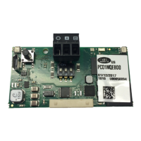
• Compressor protection for size 290 –
A communications module installed in the
compressor electrical box provides advanced
diagnostics, protection and communications, that
enhance compressor performance and reliability.
Fault status and LED annunciation
■ High / low pressure faults (HP/LP)
• Normally closed high and low pressure
switches will protect both circuits of the water
source heat pump from excessively high or low
refrigerant pressure conditions. The MicroTech
III monitors these switches individually. If either
compressor is running and the high pressure
switch for that circuit opens that compressor
will shutdown immediately. The MicroTech III
will enter "compressor faili replace" mode which
will allow the other circuit to operate normally
while it is able. If the LP switch remains open for
either circuit for the Low Pressure Time Delay
(default is 30 seconds) that compressor will
shutdown immediately. The MicroTech III will enter
"compressor faili replace" mode which will allow
the other circuit to operate normally while it is
able. If both compressors are off on a high or low
pressure fault the MicroTech III will go into Fault
mode and neither compressor is available.
MicroTech III LED Status – High/Low Pressure Faults
Pressure Yellow Green Red
HP Off Off Flash
LP Off Off Solid
Note: Circuit 2 faults are annunciated on the I/O expan-
sion module.
See Table 9 on page 19.
When the unit is in high or low pressure fault modes the
following occurs:
• The failed compressor de-energizes.
• The fault terminal (A) energizes (fault). A to R will
be used to indicate an alarm signal.
■ Low suction temperature fault heating
• The control will attempt to recover either circuit from
a low suction temperature condition by defrosting
the water heat exchanger(s) (coaxial coil). See
"Defrost process operation:" on page 14 for
details.
MICroteCh III unIt Controller

 Loading...


