OM 1239 5 www.DaikinApplied.com
MicroTech III unit controller and I/O
expansion module connections
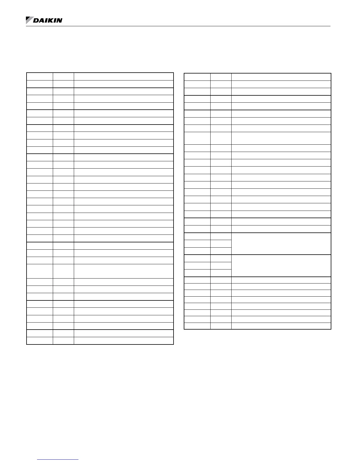
Table 2: MicroTech III unit controller terminals locations
and descriptions
H1 – 1 24 24 VAC Power Input
H1 – 2 C 24 VAC common
H2 – 1 SL1 Fan Main Output – Switched L1
H2 – 2 Blank Terminal
H2 – 3 N Fan Main Output – Neutral
H3 – 1 HP1-1 Comp High Pressure Switch (HP1) Input Terminal 1
H3 – 2 HP1-2 Comp High Pressure Switch (HP1) Input Terminal 2
H4 – 1 1 Discharge Air Temp Sensor – Common
H4 – 2 Discharge Air Temp Sensor – Signal
H4 – 3 Leaving Water Temp Sensor – Common
H4 – 4 Leaving Water Temp Sensor – Signal
H5 – 1 1 I/O Expansion Module Common (Gnd)
H5 – 2 I/O Expansion Module Common (Gnd)
H5 – 3 I/O Expansion Module +5 VDC
H5 – 4 I/O Expansion Module SPI CE1
H5 – 5 I/O Expansion Module SPI CLK
H5 – 6 I/O Expansion Module SPI OUT
H5 – 7 I/O Expansion Module SPI IN
H5 – 8 I/O Expansion Module +12 VDC
H5 – 9 I/O Expansion Module 24 VAC
H5 – 10 I/O Expansion Module 24 VAC
H5 – 11 No Connection
H5 – 12 No Connection
H6 – 1 1 Condensate Overow Signal Input
H6 – 2 Compressor Suction Temp Sensor (LT1) – Common
H6 – 3 Compressor Suction Temp Sensor (LT1) – Signal
H6 – 4
Compressor Low Pressure Switch (LP1) –
Source Voltage
H6 – 5 Compressor Low Pressure Switch (LP1) – Signal
H6 – 6 Reversing Valve – Common
H6 – 7 Reversing Valve – Output
H7 – 1 1 No Connection
H7 – 2 No Connection
H7 – 3 Red LED Output
H7 – 4 Green LED Output
H7 – 5 Yellow LED Output
H7 – 6 Red-Green-Yellow LED Common
H8 – 1 1 Isolation Valve/Pump Request Relay N/O
H8 – 2 Isolation Valve/Pump Request Relay N/C
H8 – 3 24 VAC Common
H9 – 1 1 Return Air Temp – Signal
H9 – 2 Return Air Temp* – Common
TB1 – 1 1 Room Sensor – Status LED Output
TB1 – 2 2 Room Sensor – Fan Mode & Unit Mode Switches
TB1 – 3 3 Room Sensor – Setpoint Adjust Potentiometer
TB1 – 4 4
Room Sensor – Room Temp Sensor & Tenant
Override
TB1 – 5 5 Room Sensor – DC Signal Common
TB2 – 1 R 24 VAC
TB2 – 2 A Alarm Output
TB2 – 3 W2 Thermostat – Heat Stage #2 (W2) Input
TB2 – 4 W1 Thermostat – Heat Stage #1 (W1) Input
TB2 – 5 Y2 Thermostat – Cool Stage #2 (Y2) Input
TB2 – 6 Y1 Thermostat – Cool Stage #1 (Y1) Input
TB2 – 7 G Thermostat – Fan Input
TB2 – 8 O Thermostat – Heat Stage #3 (W3) Input
TB2 – 9 C 24 VAC Common
TB3 – 1 E Emergency Shutdown Input
TB3 – 2 U Unoccupied Input
L1 – 1 L1 - 1
24 VAC Power inL1 – 2 L1 - 2
L1 – 3 L1 - 3
N1 N1
24 VAC CommonN2 N2
N3 N3
CN_LON1 – 1 CN_LON1 GND
CN_LON1 – 2 + 5 VDC
CN_LON1 – 3 SPI CE (SPI Select To Communications Board)
CN_LON1 – 4 SPI CLK (Master Clock)
CN_LON1 – 5 SPI OUT (MOSI)
CN_LON1 – 6 SPI IN (MISO)
CN_LON1 – 7 INT0 (SPI Ready To Baseboard)
CN_LON1 – 8 No Connection
* Can have return air temperature sensor connected at H9 while the
room sensor is connected to TB1, pin 4 (room temp sensor and ten-
ant override)
MICroteCh III unIt Controller

 Loading...


