OM 1239 23 www.DaikinApplied.com
Unit options
There are two dehumidication modes of operation:
1. Hot Gas Reheat Dehumidication with Temperature
Control.
2. Hot Gas Reheat Dehumidication.
Hot gas reheat with temperature
control application
Hot Gas Reheat with Temperature Control uses a
combination of 2-stage thermostat and humidistat to
optimize unit capacity and for maximum latent capacity
while decreasing room humidity levels.
■ Operation:
A call for heating or cooling has a higher priority
than a call for dehumidication. Dehumidication is
allowed only if the room temperature is satised. If the
controller detects the need for heating or cooling, or if
the Humidistat is no longer calling for dehumidication,
dehumidication mode will be suspended.
Dehumidication mode will enable both 3-way hot gas
bypass valve, sending hot superheated refrigerant to the
hot gas reheat coils while running the compressor at full
load and the fan.
Hot gas reheat dehumidication
only
■ Operation:
In applications where only dehumidication is needed,
the humidistat can be wired to TB1-1 on the Microtech
III unit controller, allowing the WSHP unit to operate in
dehumidication mode only. The unit will only respond to
a call for dehumidication.
■ Items required:
• Humidistat
■ Unit control settings:
• I/O Expansion Module Jumper Settings:
• JP5=Shorted
• JP6=Open
■ Wiring:
Figure 10: Unit and humidistat-dehumidification only
wiring diagram
Unit Base Board TB2 Thermostat
R RC 24VAC
RH 24VAC
C C 24VAC Common
G G Fan
Y1 Y Cool Stage #1
Y2 Y2 Cool Stage #2
W1 W1 Heat Stage #1
W2 W2 Heat Stage #2
O W3 Heat Stage #3
A L Alarm Input
I/O Expansion Module TB1
Humidistat
1 D/A Dehumidication
2 W4 Heat Stage #4
■ Items required:
• Unit with Hot Gas Reheat option
• Humidistat and a Thermostat OR Digitally
Adjustable Wall Sensor
■ Unit control settings:
• I/O Expansion Module Jumper Settings:
• JP5 = Shorted
• JP6 = Open
■ Wiring:
• Thermostat (Part No. 910121750)
Sensor (Part No. 910129095 or 910129096)
Combination:
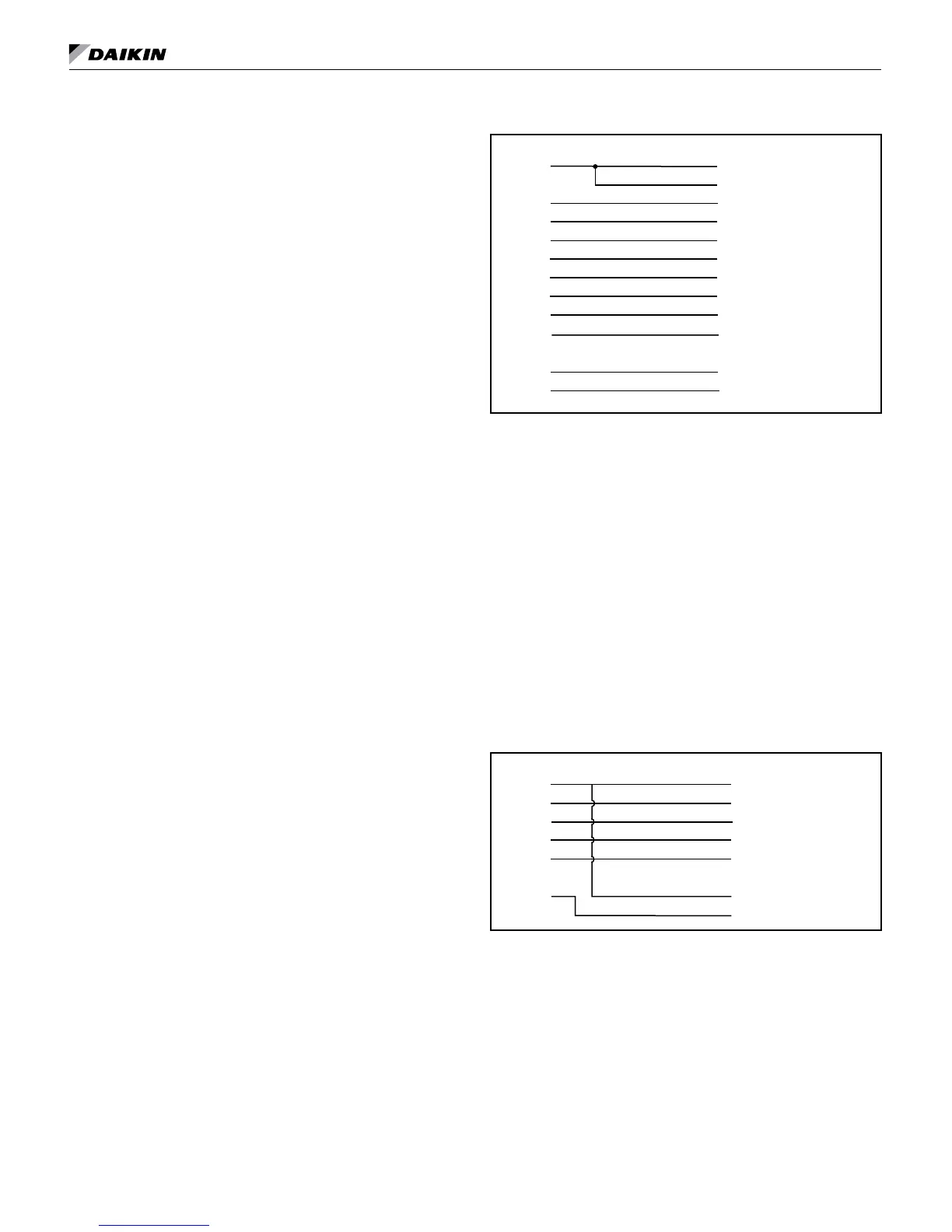
Figure 11: Thermostat and humidistat combination for hot
gas reheat dehumidification wiring diagram
Unit Thermostat
R R 24VAC
C C Common
G G Fan
Y1 Y1 Cool Stage 1
Y2 Y2 Cool Stage 2
Humidistat
TB-1 R 24VAC
DH Dehumid
• Digitally adjustable room temperature sensor (Part
No. 910121754)
MICroteCh III unIt Controller

 Loading...


