12 Technical data
Installer reference guide
26
AZAS71~140M_V1+Y1
Sky Air Active-series
4P486048-1A – 2017.08
12 Technical data
A subset of the latest technical data is available on the regional Daikin website (publicly accessible). The full set of latest technical data is
available on the Daikin extranet (authentication required).
12.1 Overview: Technical data
This chapter contains information about:
• Service space
• Piping diagram
• Wiring diagram
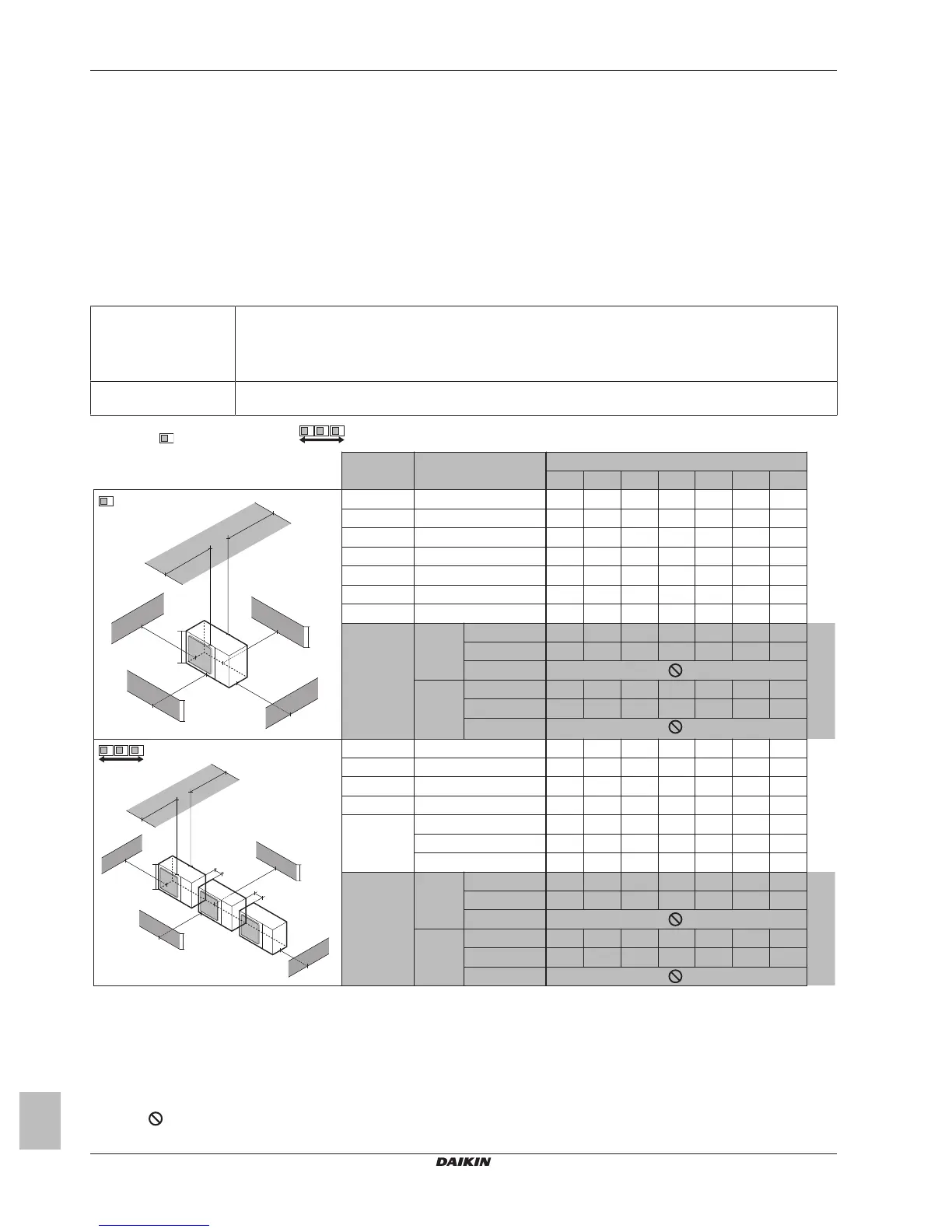
12.2 Service space: Outdoor unit
Suction side In the illustrations below, the service space at the suction side is based on 35°CDB and cooling operation. Foresee
more space in the following cases:
▪ When the suction side temperature regularly exceeds this temperature.
▪ When the heat load of the outdoor units is expected to regularly exceed the maximum operating capacity.
Discharge side Take refrigerant piping work into account when positioning the units. If your layout does not match with any of the
layouts below, contact your dealer.
Single unit (
) | Single row of units ( )
A~E
a b c d e e
B
e
D
a
b
c
d
e
e
B
e
D
A
B
C
D
E
B
H
U
H
D
H
B — ≥100
A, B, C — ≥250 ≥100 ≥100
B, E — ≥100 ≥1000 ≤500
A, B, C, E — ≥250 ≥150 ≥150 ≥1000 ≤500
D — ≥500
D, E — ≥500 ≥1000 ≤500
B, D — ≥100 ≥500
B, D, E
1+2
1
H
B
<H
D
H
B
≤½H
U
≥250 ≥750 ≥1000 ≤500
½H
U
<H
B
≤H
U
≥250 ≥1000 ≥1000 ≤500
H
B
>H
U
H
B
>H
D
H
D
≤½H
U
≥100 ≥1000 ≥1000 ≤500
½H
U
<H
D
≤H
U
≥200 ≥1000 ≥1000 ≤500
H
D
>H
U
A, B, C — ≥250 ≥300 ≥1000
A, B, C, E — ≥250 ≥300 ≥1000 ≥1000 ≤500
D — ≥1000
D, E — ≥1000 ≥1000 ≤500
B, D H
D
>H
U
≥300 ≥1000
H
D
≤½H
U
≥250 ≥1500
½H
U
<H
D
≤H
U
≥300 ≥1500
B, D, E H
B
<H
D
H
B
≤½H
U
≥300 ≥1000 ≥1000 ≤500
½H
U
<H
B
≤H
U
≥300 ≥1250 ≥1000 ≤500
H
B
>H
U
H
B
>H
D
H
D
≤½H
U
≥250 ≥1000 ≥1000 ≤500
½H
U
<H
D
≤H
U
≥300 ≥1000 ≥1000 ≤500
H
D
>H
U
H
B
H
D
H
U
(mm)
H
U
a
b
≥100
≥100
c
d
e
e
B
e
D
A
B
C
D
E
H
B
H
D
A,B,C,D Obstacles (walls/baffle plates)
E Obstacle (roof)
a,b,c,d,e Minimum service space between the unit and obstacles A, B, C, D and E
e
B
Maximum distance between the unit and the edge of obstacle E, in the direction of obstacle B
e
D
Maximum distance between the unit and the edge of obstacle E, in the direction of obstacle D
H
U
Height of the unit
H
B
,H
D
Height of obstacles B and D
1 Seal the bottom of the installation frame to prevent discharged air from flowing back to the suction side through the bottom of the unit.
2 Maximum two units can be installed.
Not allowed

 Loading...