12 Technical data
Installer reference guide
27
AZAS71~140M_V1+Y1
Sky Air Active-series
4P486048-1A – 2017.08
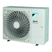
Multiple rows of units ( )
b (mm)
≥1000
≥200
≥2000
≥100
≥3000
≥1500
b
≥100
≥100
≥100
≥100
≥250
≥250
H
B
H
U
H
B
≤½H
U
b≥250
½H
U
<H
B
≤H
U
b≥300
H
B
>H
U
H
B
H
U
Stacked units (max. 2 levels) ( )
A1
A2
≥500
≥1000
A2
≥500
≥300
≥100
≥100
B1
A2
B2
≥100
≥300
≥100
≥100
B2
≥100
≥1000
B2
A1=>A2 (A1) If there is danger of drainage dripping and freezing between the upper and lower units…
(A2) Then install a roof between the upper and lower units. Install the upper unit high enough above the lower unit to prevent ice buildup at the
upper unit's bottom plate.
B1=>B2 (B1) If there is no danger of drainage dripping and freezing between the upper and lower units…
(B2) Then it is not required to install a roof, but seal the gap between the upper and lower units to prevent discharged air from flowing back to the
suction side through the bottom of the unit.
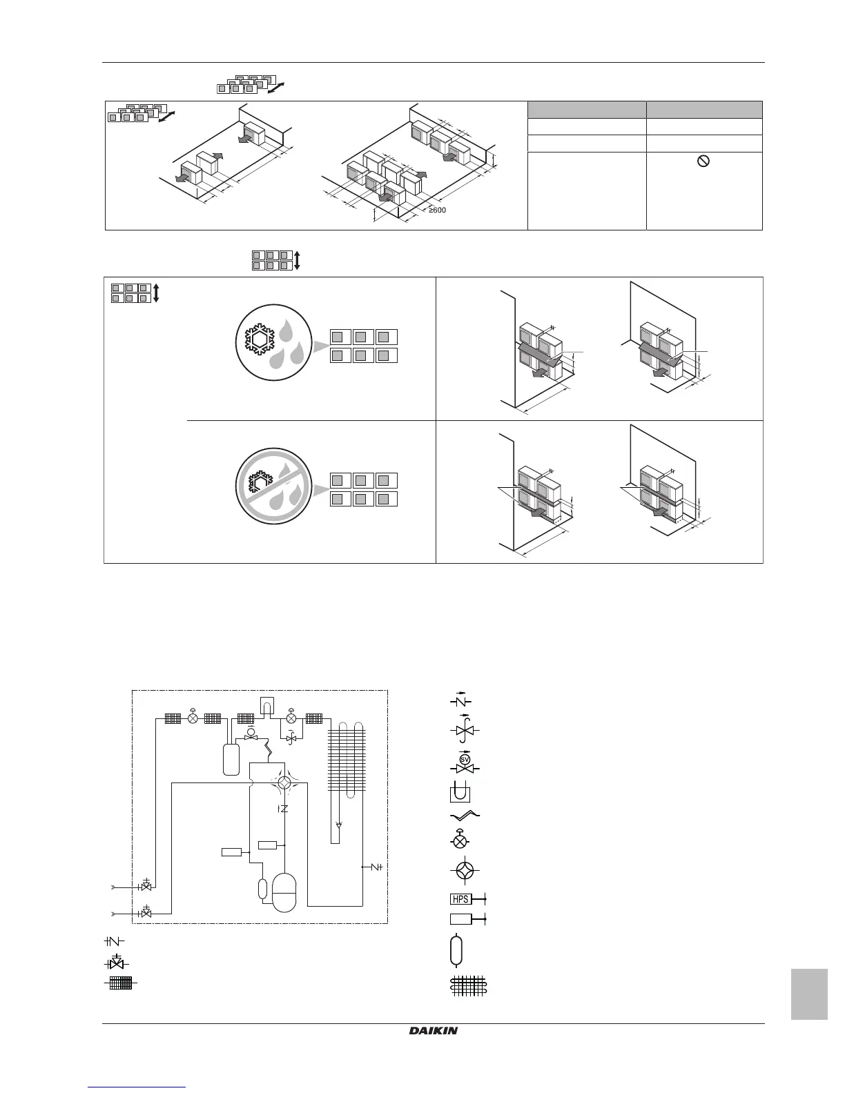
12.3 Piping diagram: Outdoor unit
Charge port / Service port (with 5/16" flare)
Stop valve
Filter
Check valve
Pressure relief valve
Solenoid valve
Heat sink (PCB)
Capillary tube
Electronic expansion valve
4‑way valve
High pressure switch
Low pressure switch
Compressor accumulator
Heat exchanger

 Loading...