English 6
• Use the following items for the refrigerant piping.
Mat
erial: Jointless phosphor-deoxidized copper pipe
Size: See “6-5 Example of connection” to determine the cor-
rect size.
Thickness: Select a thickness for the refrigerant piping which
complies with national and local laws.
Refrigerant pipe (Gas pipe and Liquid pipe) and refrigerant
branch must meet the condition of design pressure 3.3MPa.
If it is not possible to confirm, use the refrigerant branch kit
selected with 6-5 Example of connection.
Existing pipes must meet the condition of design pressure
3.3MPa.
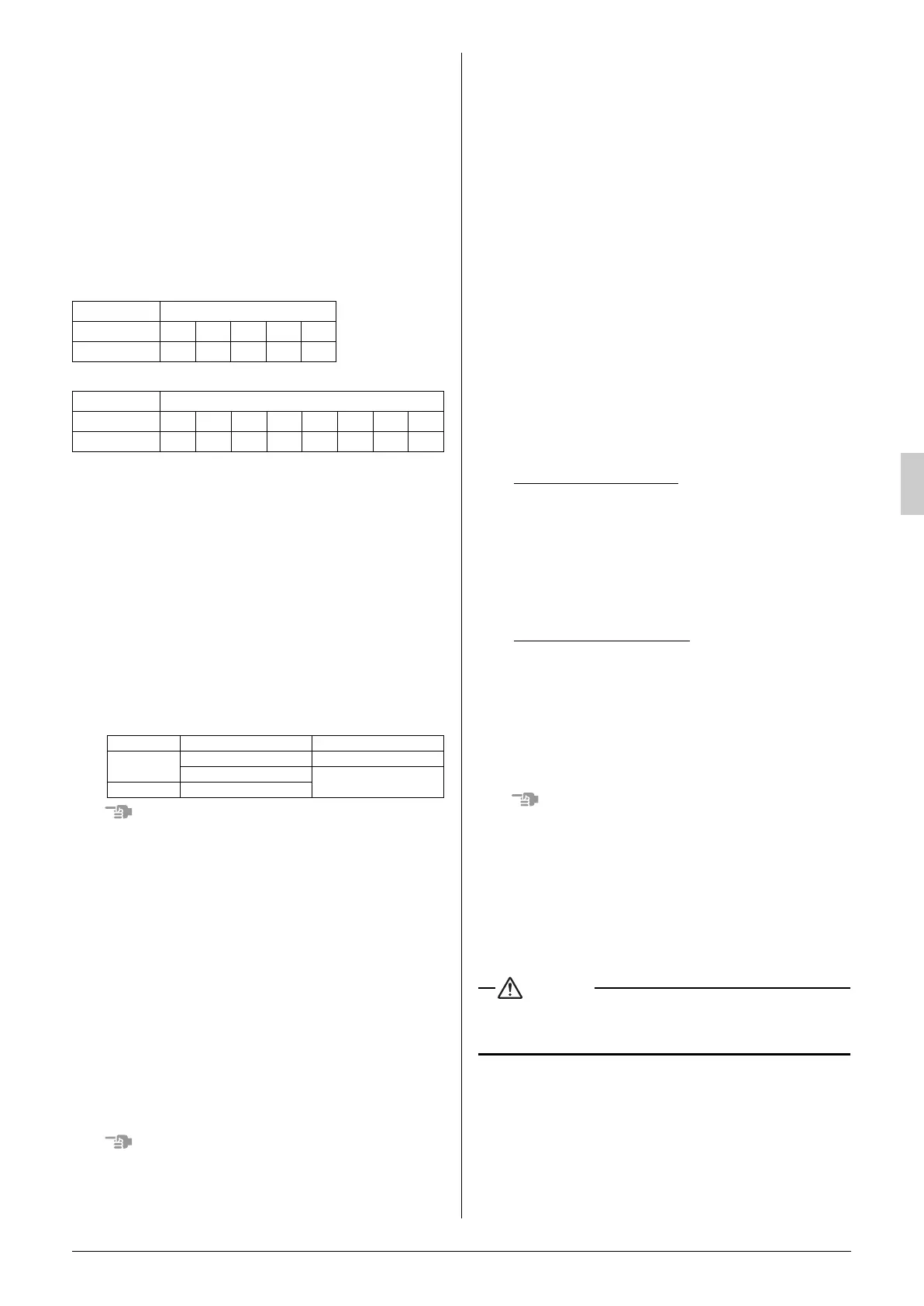
Specificaly, to confirm that there are no corrosion and the pipe
thickness must not be less than the smallest thickness below.
Temper grade (O type, 1/2H type) in the table indicate the
material types specified in JIS H 3300.
(unit: mm)
* In case of bending 3×D or more (D: O.D. of refrigerant pipe)
(unit: mm)
• For piping work, follow the maximum tolerated length, difference
in height, and length after a branch indicated in the “6-5 Example
of connection”.
• A refrigerant branching kit (sold separately) is needed for piping
branches and connection of piping between outdoor unit (in case
of multi system).
Use only separately sold items selected specifically according to
the refrigerant branch kit selection in the “6-5 Example of con-
nection”.
• If any tapered pipes are used as branching pipes, replace them.
• If the diameter of existing piping differs from that of outdoor/BS/
indoor units, use a locally-procured irregular socket.
6-2 Protection against contamination
when installing pipes
Protect the piping to prevent moisture, dirt, dust, etc. from
entering the piping.
Exercise special caution to prevent dirt or dust when passing pip-
ing thr
ough holes in walls and when passing pipe edges to the
exterior.
6-3 Pipe connection
• Be sure to perform nitrogen permutation or nitrogen blow
when brazing. (Refer to figure 11)
Brazing without performing nitrogen permutation or nitrogen
blow into the piping will create large quantities of oxidized film
on the inside of the pipes, adversely affecting valves and com-
pressors in the refrigerating system and preventing normal
operation.
(Refer to figure 11)
1. Refrigerant pipe
2. Location to be brazed
3. Nitrogen
4. Taping
5. Handy valve
6. Regulator
• The pressure regulator for the nitrogen released when doing
the brazing should be set to 0.02 MPa (about 0.2kg/cm
2
:
Enough to feel a slight breeze on your cheek).
Do not use anti-oxidants when brazing the pipe joints.
Resi
due can clog pipes and break equipment.
6-4 Connecting the refrigerant piping
1.
Direction to bring out the pipes
The local interunit piping can be connected either forward or to
the sides (taken out through the bottom) as shown in the figure
12.
(When passing out through the bottom, use the knock hole in the
bottom frame.)
(Refer to figure 12)
1. Left-side connection
2. Front connection
3. Right-side connection
Precautions when knocking out knock holes
• Open knock hole in the base frame by drilling the 4 concave
around it with a 6mm bit. (Refer to figure 13)
(Refer to figure 13)
1. Knock hole
2. Drill
3. Concave section
• Be sure to avoid damaging the casing
• After knocking out the holes, we recommend you remove any
burrs and paint them using the repair paint to prevent rusting.
• When passing electrical wiring through the knock holes, protect
the wiring with a conduit or bushings, making sure not to damage
the wiring.
2.
Removing Pinch Piping
• When connecting refrigerant piping to an outdoor unit, remove
the pinch piping.
• Pinch piping should be removed using the procedure below.
• Heat Pump series (RQ(C)YQ)
(Refer to figure 14.1)
1. Pi
nch piping (2 pipings)
2. Piping is not used
3. Note: Do not dissolve the brazing
<Procedure>
• Confirm the shutoff valve is closed.
• Connect a charge hose to the service port on the liquid side
and suction gas side shutoff valves and remove the gas from
the pinch piping.
• After removing the gas from the pinch piping, dissolve the
brazing using a burner and remove the pinch piping.
• Heat Recovery series (RQCEQ)
(Refer to figure 14.2)
1. Pi
nch piping (3 pipings)
2. Note: Do not dissolve the brazing
<Procedure>
• Confirm the shutoff valve is closed.
• Connect a charge hose to the service port on the liquid side,
suction gas side and HP/LP gas side shutoff valves and
remove the gas from the pinch piping.
• After removing the gas from the pinch piping, dissolve the
brazing using a burner and remove the pinch piping.
(Refer to figure 14.3)
• W
hen the oil flows out of the cutting part, cutoff the pinch piping
(large) with a pipe cutter.
1. Service port
2. Valve cover
3. Open
4. Close
5. Piping onsite
6. Cutoff
7. Pinch piping (Large)
8. Pinch piping (small)
After removing the gas, remove the pinch piping.
An
y gas remaining inside may blow off the pinch piping when you dis-
solve the brazing, causing damage.
Tem
per grade O type
outer diameter
φ6.4 φ9.5 φ12.7 φ15.9 φ19.1
smallest thickness
0.4* 0.5* 0.7* 0.9* 1.0*
Temper grade 1/2H type
outer diameter
φ19.1 φ22.2 φ25.4 φ28.6 φ31.8 φ34.9 φ38.1 φ41.3
smallest thickness
0.6 0.6 0.7 0.8 0.9 1.0 1.1 1.1
Place Installation period Protection method
Outdoor
More than a month Pinch the pipe
Less than a month
Pinch or tape the pipe
Indoor Regardless of the period
01_EN_3P226891_9.fm Page 6 Tuesday, December 1, 2009 4:38 PM
 Loading...