English 4
• Heat Recovery series (RQEQ)
(Ref
er to figure 1)
1. Clamps, Operation manual, etc.
2. Accessory pipes
3. Installation manual
Do not throw away any of the accessories until installation is com-
plete.
2
-3 Option accessory
To install the outdoor units, the following optional parts are also
required. To select an optimum kit, refer to “6-5 Example of connec-
tion”.
• Refrigerant branching kit
If it is not possible to use existing branch piping or if it is necessary to
install new piping when installing refrigerant piping to BS/indoor
units, the following parts are required. (Be sure to use branch piping
of at least the design pressure of 3.3 MPa.)
• Heat Pump series (RQ(C)YQ)
• Heat Recovery series (RQCEQ)
• Outdoor unit multi connection piping kit
• Heat Pump series (RQ(C)YQ)
• Heat Recovery series (RQCEQ)
Make sure that any separately purchased accessories are designed
for us
e with R410A.
2-4 Technical and Electrical specifications
Refer to the Engineering Data Book for the complete list of specifica-
tions.
2-5 Main components
For main components and function of the main components, refer to
the Engineering Data Book.
2-6 Installation Process
Figure 2 shows the installation process. Install in the order of the
steps shown.
(Refer to figure 2)
1. “3. SELECTION OF LOCATION”
2. “4. INSPECTING AND HANDLING THE UNIT”
3. “5. PLACING THE UNIT”
4. “6. REFRIGERANT PIPING”
5. “7. FIELD WIRING”
6. “8. AIR TIGHT TEST AND VACUUM DRYING”
7. “9. PIPE INSULATION”
8. “10. CHECKING OF DEVICE AND INSTALLATION
CONDITIONS”
9. “11. ADDITIONAL REFRIGERANT CHARGE AND
CHECK OPERATION”
10. “13. TEST RUN”
11. Operations which require the power to be turned on.
3. SELECTION OF LOCATION
Select a location for installation that meets the following conditions.
Get the customer’s permission.
1.
There is no danger of fire due to leakage of flammable gas.
2.
Select the location of the unit in such a way that neither the dis-
charged air nor the sound generated by the unit disturb anyone.
3.
The foundation is strong enough to support the weight of the unit
and the floor is flat to prevent vibration and noise generation.
4.
The piping length between the outdoor unit and the indoor unit
may not exceed the allowable piping length. (Refer to
“6. REFRIGERANT PIPING”)
5.
Locations where the unit’s suction vent and outlet vent do not
directly face the wind.
Wind blowing directly into the suction or outlet vents will interfere
with the unit’s operation.
If necessary, install some kind of obstruction to block the wind.
6.
The space around the unit is adequate for servicing and the min-
imum space for air inlet and air outlet is available.
(See the “Installation Space Examples” for the minimum space
requirements.)
Installation Space Examples
• The installation space requirement shown in figure 3 is a refer-
ence for cooling operation when the outdoor temperature is 35°C.
If the design outdoor temperature exceeds 35°C or the heat load
exceeds maximum capacity in all the outdoor unit, take an even
large space on the intake shown in figure 3.
• During installation, install the units using the most appropriate of
the patterns shown in figure 3 for the location in question, taking
into consideration human traffic and wind.
• If the number of units installed is more than that is shown in the
pattern in figure 3, install the units so there are no short circuits.
• As regards space in front of the unit, consider the space needed
for the local refrigerant piping when installing the units.
• If the work conditions in figure 3 do not apply, contact your dealer
or Daikin directly.
(Refer to figure 3)
1. Front side
2. No limit to wall height
3. Service space of front side
4. Service space of suction side
For Patterns 1 and 2 in figure 3:
• Wall height for the front side should be no higher than 1500
mm.
• Wall height for the suction side should be no higher than 500
mm.
• Wall height for the sides – no limit.
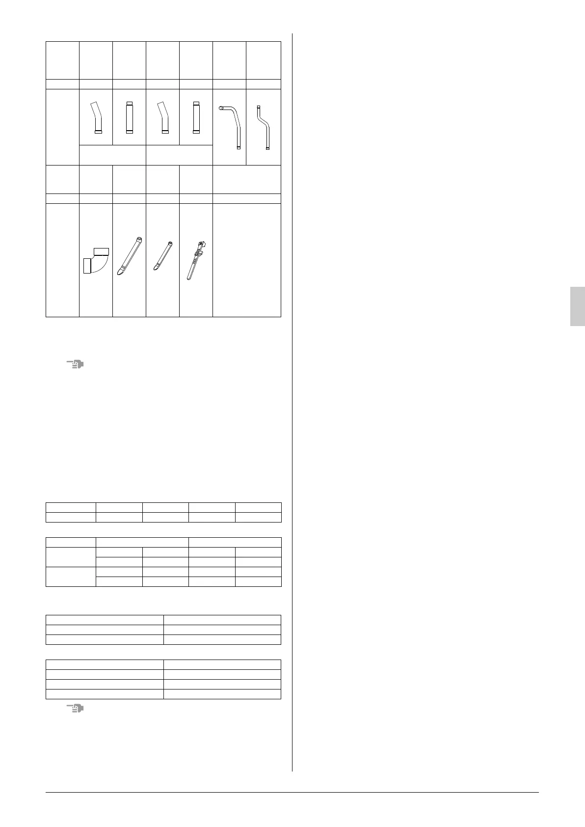
Name
Suction
gas side
accessory
pipe (1)
Suction
gas side
accessory
pipe (2)
HP/LP
gas side
accessory
pipe (1)
HP/LP
gas side
accessory
pipe (2)
Liquid side
accessory
pipe (1)
Liquid side
accessory
pipe (2)
Quantity
1 pc. 1 pc. 1 pc. 1 pc. 1 pc. 1 pc.
Shape
Q140 type:
φ
15.9,
Q180·212 type:
φ
19.1
Q140 type:
φ
12.7,
Q180·212 type:
φ
15.9
Name
L type
accessory
joint
Clamp (1) Clamp (2) Clamp (3)
Others
Quantity
2 pcs. 1 pc. 8 pcs. 1 pc. 1 pc. each item
Shape
(Large) (Small)
• Operation manual
• Installation manual
• Declaration con-
formity (PED,
EMC, MD)
• “REQUEST FOR
THE INDICATION”
label (Installation
records)
• “ADDITIONAL
REF. CHARGE”
label
REFNET header KHRP26M22H KHRP26M33H KHRP26M72H KHRP26M73H
REFNET joint KHRP26A22T KHRP26A33T KHRP26A72T KHRP26A73T
for 3 piping for 2 piping
REFNET header
- KHRP25M33H KHRP26M22H KHRP26M33H
KHRP25M72H KHRP25M73H KHRP26M72H KHRP26M73H
REFNET joint
KHRP25A22T KHRP25A33T KHRP26A22T KHRP26A33T
KHRP25A72T KHRP25A73T KHRP26A72T KHRP26A73T
Kit name
2 units BHFP22P36C
3 units BHFP22P54C
Kit name
2 units BHFP26P36C
3 units BHFP26P63C
4 units BHFP26P84C
01_EN_3P226891_9.fm Page 4 Tuesday, December 1, 2009 4:38 PM
 Loading...