19 English
10. CHECKING OF DEVICE AND INSTAL-
LA
TION CONDITIONS
Be sure to check the followings.
For electrical work
1.
Make sure there is no faulty transmission wiring or loosing of a
nut.
See “7-4 Transmission Wiring Connection Procedure”.
2.
Make sure there is no faulty power wiring and ground wiring or
loosing of a nut.
See “7-5 Power Wiring Connection Procedure”.
3.
Has the insulation of the main power circuit deteriorated?
Measure the insulation and check the insulation is above regular
value in accordance with relevant local and national regulations.
For those doing pipe work
1.
Make sure piping size is correct.
See “6-1 Selection of piping material and Refrigerant branch-
ing kit”.
2.
Make sure insulation work is done.
See “9. PIPE INSULATION”.
3.
Make sure there is no faulty refrigerant piping.
See “6. REFRIGERANT PIPING”.
11. ADDITIONAL REFRIGERANT
CHARGE AND CHECK OPERATION
The outdoor unit is charged with refrigerant when shipped from the
factory, but depending on the size and length of the piping when
installed, it may require additional charging.
For charging the additional refrigerant, follow the procedure in this
chapter.
And then carry out the check operation.
11-1 Before working
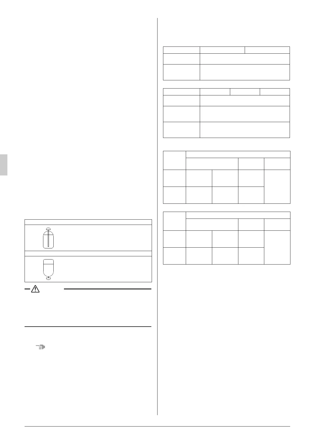
[About the refrigerant tank]
Check whether the tank has a siphon pipe before charging and place
the tank so that the refrigerant is charged in liquid form. (See the fig-
ure below.)
• Always use the proper refrigerant (R410A). If charged with the
refr
igerant containing an improper material, it may cause an
explosion or accident.
• R410A is a mixed refrigerant, so charging it as a gas will cause
the refrigerant composition to change, which may prevent normal
operation.
[S
hutoff valve operation procedure]
When operating the shutoff valve, follow the procedure instructed
below.
• Do not open the shutoff valve until “10. CHECKING OF DEVICE
AND
INSTALLATION CONDITIONS” are completed. If the shutoff
valve is left open without turning on the power, it may cause refrig-
erant to buildup in the compressor, leading insulation degrada-
tion.
• Be sure to use the correct tools.
The shutoff valve is not a back-seat type. If forced open, it might
break the valve body.
• When using a service port, use the charge hose.
• After tightening the cap, make sure no refrigerant gas is leaking.
[Tightening torque]
The sizes of the shutoff valves on each model and the tightening
torque for each size are listed in the table below.
<Size of Shutoff Valve>
• Heat Pump series (RQ(C)YQ)
• Heat Recovery series (RQCEQ)
<Tightening torque>
• Heat Pump series (RQ(C)YQ)
• Heat Recovery series (RQCEQ)
(Refer to figure 33)
1. Service port
2. Cap
3. Hex holes
4. Shaft (valve body)
5. Seal section
[To open]
1.
Remove the cap and turn the shaft counterclockwise with the
hexagon wrench (JISB4648).
2.
Turn it until the shaft stops.
3.
Make sure to tighten the cap securely.
(For the tightening torque, refer to the item <Tightening Torque>.)
[To close]
1.
Remove the cap and turn the shaft clockwise with the hexagon
wrench (JISB4648).
2.
Securely tighten the valve until the shaft contacts the main body
seal.
3.
Make sure to tighten the cap securely.
(For the tightening torque, refer to the item <Tightening Torque>.)
With siphon pipe
Other tanks
Stand the tank upright and charge.
(The siphon pipe goes all the way inside,
so the tank does not need be put
upside-down charge in liquid form.)
Stand the tank upside-down and charge.
Usage
Q140 ty
pe Q180 type
Liquid side shutoff
valve
φ 9.5
Gas side shutoff
valve
φ 15.9
Q180 type is correspond to the field piping
φ19.1 by accessory piping.
Usage
Q140 type Q180 type Q212 type
Liquid side shutoff
valve
φ 9.5
Gas side shutoff
valve
φ 15.9
Q180 and Q212 type are correspond to field
piping φ19.1 by accessory piping.
HP/LP gas side
shutoff valve
φ 15.9
Q140 type is correspond to field piping φ12.7
by accessory piping.
Shutoff
valve size
Tightening torque N·m (Turn clockwise to close)
Shaft (valve body)
Cap
(valve lid)
Service port
φ 9.5 5.4 ~ 6.6
Hexagonal
wrench
: 4 mm
13.5 - 16.5
11.5 ~ 13.9
φ 15.9 13.5 ~ 16.5
Hexagonal
wrench
: 6 mm
22.5 - 27.5
Shutoff
valve size
Tightening torque N·m (Turn clockwise to close)
Shaft (valve body)
Cap
(valve lid)
Service port
φ 9.5 5.4 ~ 6.6
Hexagonal
wrench
: 4 mm
13.5 ~ 16.5
11.5 ~ 13.9
φ 15.9 13.5 ~ 16.5
Hexagonal
wrench
: 6 mm
22.5 ~ 27.5
01_EN_3P226891_9.fm Page 19 Tuesday, December 1, 2009 4:38 PM
 Loading...