15 Electrical installation
Installation and operation manual
31
RYYQ+RYMQ+RXYQ8~20U7Y1B
VRV IV+ heat pump
4P546220-1C – 2020.10
WARNING
ALWAYS use multicore cable for power supply cables.
15.1 About electrical compliance
This equipment complies with:
▪ EN/IEC 61000‑3‑11
provided that the system impedance Z
sys
is
less than or equal to Z
max
at the interface point between the user's
supply and the public system.
▪ EN/IEC 61000‑3‑11 = European/International Technical
Standard setting the limits for voltage changes, voltage
fluctuations and flicker in public low-voltage supply systems for
equipment with rated current ≤75A.
▪ It is the responsibility of the installer or user of the equipment to
ensure, by consultation with the distribution network operator if
necessary, that the equipment is connected only to a supply
with a system impedance Z
sys
less than or equal to Z
max
.
▪ EN/IEC 61000‑3‑12 provided that the short-circuit power S
sc
is
greater than or equal to the minimum S
sc
value at the interface
point between the user's supply and the public system.
▪ EN/IEC 61000‑3‑12 = European/International Technical
Standard setting the limits for harmonic currents produced by
equipment connected to public low-voltage systems with input
current >16A and ≤75A per phase.
▪ It is the responsibility of the installer or user of the equipment to
ensure, by consultation with the distribution network operator if
necessary, that the equipment is connected only to a supply
with a short-circuit power S
sc
greater than or equal to the
minimum S
sc
value.
Model Z
max
(Ω) Minimum S
sc
value (kVA)
RYYQ8/RYMQ8/RXYQ8 — 4050
RYYQ10/RYMQ10/RXYQ10 — 5535
RYYQ12/RYMQ12/RXYQ12 — 6038
RYYQ14/RYMQ14/RXYQ14 — 6793
RYYQ16/RYMQ16/RXYQ16 — 7547
RYYQ18/RYMQ18/RXYQ18 — 8805
RYYQ20/RYMQ20/RXYQ20 — 9812
RYYQ22/RXYQ22 — 11573
RYYQ24/RXYQ24 — 11597
RYYQ26/RXYQ26 — 12831
RYYQ28/RXYQ28 — 13585
RYYQ30/RXYQ30 — 14843
RYYQ32/RXYQ32 — 15094
RYYQ34/RXYQ34 — 16352
RYYQ36/RXYQ36 — 17359
RYYQ38/RXYQ38 — 19397
RYYQ40/RXYQ40 — 20378
RYYQ42/RXYQ42 — 20629
RYYQ44/RXYQ44 — 21132
RYYQ46/RXYQ46 — 21887
RYYQ48/RXYQ48 — 22641
RYYQ50/RXYQ50 — 23899
RYYQ52/RXYQ52 — 25157
RYYQ54/RXYQ54 — 26415
INFORMATION
Multi units are standard combinations.
15.2 Safety device requirements
The power supply must be protected with the required safety
devices, i.e. a main switch, a slow blow fuse on each phase and an
earth leakage protector in accordance with the applicable legislation.
For standard combinations
Selection and sizing of the wiring should be done in accordance with
the applicable legislation based on the information mentioned in the
table below.
Model Minimum
circuit
ampacity
Recommended
fuses
RYYQ8/RYMQ8/RXYQ8 16.1A 20A
RYYQ10/RYMQ10/RXYQ10 22.0A 25A
RYYQ12/RYMQ12/RXYQ12 24.0A 32A
RYYQ14/RYMQ14/RXYQ14 27.0A 32A
RYYQ16/RYMQ16/RXYQ16 31.0A 40A
RYYQ18/RYMQ18/RXYQ18 35.0A 40A
RYYQ20/RYMQ20/RXYQ20 39.0A 50A
For all models:
▪ Phase and frequency: 3N~50Hz
▪ Voltage: 380~415V
▪ Transmission line section: 0.75~1.25 mm
2
, maximum length is
1000 m. If the total transmission wiring exceeds these limits, it
may result in communication error.
For non-standard combinations
Calculate the recommended fuse capacity.
Formula Calculate, by adding the minimum circuit amps of each
used unit (according to the table above), multiply the
result by 1.1 and select the next higher recommended
fuse capacity.
Example Combining the RXYQ30 by using the RXYQ8,
RXYQ10, and RXYQ12.
▪ Minimum circuit ampacity of the RXYQ8=16.1A
▪ Minimum circuit ampacity of the RXYQ10=22.0A
▪ Minimum circuit ampacity of the RXYQ12=24.0A
Accordingly, the minimum circuit ampacity of the
RXYQ30=16.1+22.0+24.0=62.1A
Multiply the above result by 1.1: (62.1A×1.1)=68.3A,
so the recommended fuse capacity would be 80A.
NOTICE
When using residual current operated circuit breakers, be
sure to use a high-speed type 300 mA rated residual
operating current.
15.3 Field wiring: Overview
Field wiring consists of:
▪ power supply (including earth),
▪ DIII transmission wiring between communication box and outdoor
unit,
▪ RS‑485 transmission wiring between communication box and
monitoring system.
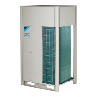
Example:
 Loading...
