16 Configuration
Installation and operation manual
34
RYYQ+RYMQ+RXYQ8~20U7Y1B
VRV IV+ heat pump
4P546220-1C – 2020.10
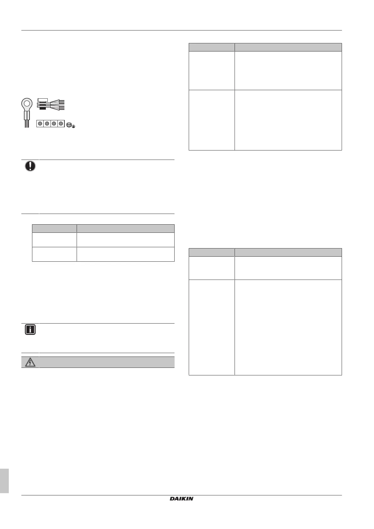
j When connecting the earth wire, it is recommended to
perform curling.
Multiple outdoor units
To connect the power supply for multiple outdoor units to each other,
ring tongues have to be used. No bare cable can be used.
In that case, the ring washer that is installed by default should be
removed.
Attach both cables to the power supply terminal as indicated below:
15.9 To check the insulation resistance
of the compressor
NOTICE
If, after installation, refrigerant accumulates in the
compressor, the insulation resistance over the poles can
drop, but if it is at least 1MΩ, then the unit will not break
down.
▪ Use a 500V mega-tester when measuring insulation.
▪ Do NOT use a mega-tester for low voltage circuits.
1 Measure the insulation resistance over the poles.
If Then
≥1MΩ Insulation resistance is OK. This procedure
is finished.
<1MΩ Insulation resistance is not OK. Go to the
next step.
2 Turn ON the power and leave it on for 6hours.
Result: The compressor will heat up and evaporate any
refrigerant in the compressor.
3 Measure the insulation resistance again.
16 Configuration
INFORMATION
It is important that all information in this chapter is read
sequentially by the installer and that the system is
configured as applicable.
DANGER: RISK OF ELECTROCUTION
16.1 Making field settings
16.1.1 About making field settings
To continue the configuration of the VRV IV heat pump system, it is
required to give some input to the PCB of the unit. This chapter will
describe how manual input is possible by operating the push
buttons/DIP switches on the PCB and reading the feedback from the
7‑segment displays.
Making settings is done via the master outdoor unit.
Next to making field settings it is also possible to confirm the current
operation parameters of the unit.
Push buttons and DIP switches
Item Description
Push buttons By operating the push buttons it is possible to:
▪ Perform special actions (automatic
refrigerant charge, testrun, etc).
▪ Perform field settings (demand operation,
low noise, etc).
DIP switches By operating the DIP switches it is possible to:
▪ DS1 (1): COOL/HEAT selector (refer to the
manual of the cool/heat selector switch).
OFF=not installed=factory setting
▪ DS1 (2~4): NOT USED. DO NOT CHANGE
THE FACTORY SETTING.
▪ DS2 (1~4): NOT USED. DO NOT CHANGE
THE FACTORY SETTING.
See also:
▪ "Field setting components"[434]
▪ "To access the field setting components"[435]
PC configurator
For VRV IV heat pump system it is alternatively possible to make
several commissioning field settings through a personal computer
interface (for this, option EKPCCAB* is required). The installer can
prepare the configuration (off-site) on PC and afterwards upload the
configuration to the system.
See also: "To connect the PC configurator to the outdoor
unit"[437].
Mode 1 and 2
Mode Description
Mode 1
(monitoring
settings)
Mode1 can be used to monitor the current
situation of the outdoor unit. Some field setting
contents can be monitored as well.
Mode 2
(field settings)
Mode2 is used to change the field settings of
the system. Consulting the current field setting
value and changing the current field setting
value is possible.
In general, normal operation can be resumed
without special intervention after changing field
settings.
Some field settings are used for special
operation (e.g., 1 time operation, recovery/
vacuuming setting, manual adding refrigerant
setting, etc.). In such a case, it is required to
abort the special operation before normal
operation can restart. It will be indicated in
below explanations.
See also:
▪ "To access mode 1 or 2"[435]
▪ "To use mode 1"[435]
▪ "To use mode 2"[435]
▪ "Mode 1: Monitoring settings"[436]
▪ "Mode 2: Field settings"[436]
16.1.2 Field setting components
Location of the 7‑segment displays, buttons and DIP switches:

 Loading...