20 Technical data
Installation and operation manual
46
RYYQ+RYMQ+RXYQ8~20U7Y1B
VRV IV+ heat pump
4P546220-1C – 2020.10
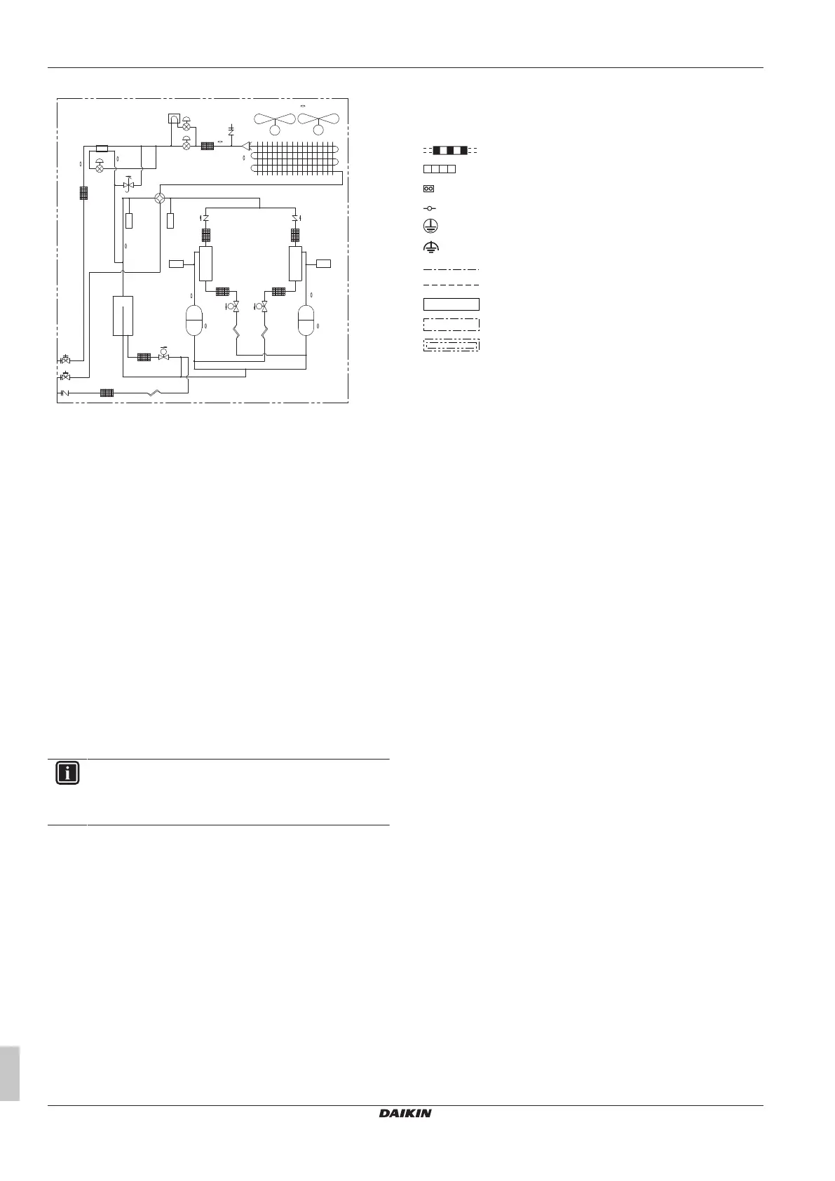
Piping diagram: RXYQ14~20
a
b
k k
nm
f
l
j
o
t
s
h
c
e
d d
e
M
sv
sv
INV INV
sv
M1C
M2C
M1F
M
M2F
(S1NPH)
(S1NPL)
(S1PH) (S2PH)
HPS
R6T
R5T
R1T
R9TR8T
R21T
R22T
R3T
HPS
r
R4T
g
x
w
a Compressor (M1C)
b Compressor (M2C)
c Heat exchanger
d Fan
e Fan motor (M1F, M2F)
f Accumulator
g Expansion valve, main (Y1E)
h Expansion valve, subcool heat exchanger (Y2E)
i Expansion valve, storage vessel (Y4E)
j Subcool heat exchanger
k Oil separator
l Solenoid valve, oil accumulator (Y2S)
m Solenoid valve, oil1 (Y3S)
n Solenoid valve, oil2 (Y4S)
o 4‑way valve, main (Y1S)
p 4‑way valve, sub (Y5S)
q Electrical component box
r Service port, refrigerant charge
s Stop valve, liquid
t Stop valve, gas
u Stop valve, equalising gas
v Heat accumulation element
w Service port
x Expansion valve, liquid cooling (Y3E)
20.3 Wiring diagram: Outdoor unit
Refer to the wiring diagram sticker on the unit. The abbreviations
used are listed below:
INFORMATION
The wiring diagram on the outdoor unit is only for the
outdoor unit. For the indoor unit or optional electrical
components, refer to the wiring diagram of the indoor unit.
1 This wiring diagram applies only to the outdoor unit.
2 Symbols (see below).
3 When using the optional adapter, refer to the installation
manual of the optional adapter
4 For connection wiring to indoor–outdoor transmission F1‑F2,
outdoor‑outdoor transmission F1‑F2, outdoor‑multi
transmission Q1‑Q2, refer to the installation manual.
5 How to use BS1~BS3 switch, refer to the "Service
Precaution" label on the electrical component box cover.
6 When operating, do NOT short-circuit the protection devices
(S1PH).
7 Only for RYYQ model
8 Only for RYYQ/RYMQ model
9 For 8~12 HP: Connector X1A (M1F) is white, connector X2A
(M2F) is red.
9 For 14~20 HP: Colours (see below).
10 Colours (see below).
Symbols:
Field wiring
Terminal block
Connector
Terminal
Protective earth
Noiseless earth
Earth wiring
Field supply
PCB
Switch box
Option
Colours:
BLK Black
RED Red
BLU Blue
WHT White
GRN Green
Legend for wiring diagram 8~12 HP:
A1P Printed circuit board (main)
A2P Printed circuit board (noise filter)
A3P Printed circuit board (inverter)
A4P Printed circuit board (fan)
A5P Printed circuit board (ABC I/P) (option)
BS1~BS3
(A1P)
Push button switch (MODE, SET, RETURN)
C* (A3P) Capacitor
DS1, DS2
(A1P)
DIP switch
E1HC Crankcase heater
E3H Drain pan heater (option)
F1U, F2U
(A1P)
Fuse (T 3.15A / 250V)
F3U Field fuse
F101U
(A4P)
Fuse
F401U,
F403U
(A2P)
Fuse
F601U,
(A3P)
Fuse
HAP (A*P) Pilot lamp (service monitor is green)
K3R (A3P) Magnetic relay
K4R (A1P) Magnetic relay (Y1S)
K5R (A1P) Magnetic relay (Y2S)
K6R (A1P) Magnetic relay (E3H)
K7R (A1P) Magnetic relay (E1HC)
K9R (A1P) Magnetic relay (Y3S)
K11R (A1P) Magnetic relay (Y5S)
L1R Reactor
M1C Motor (compressor)
M1F Motor (fan)

 Loading...