15 Electrical installation
Installation and operation manual
33
RYYQ+RYMQ+RXYQ8~20U7Y1B
VRV IV+ heat pump
4P546220-1C – 2020.10
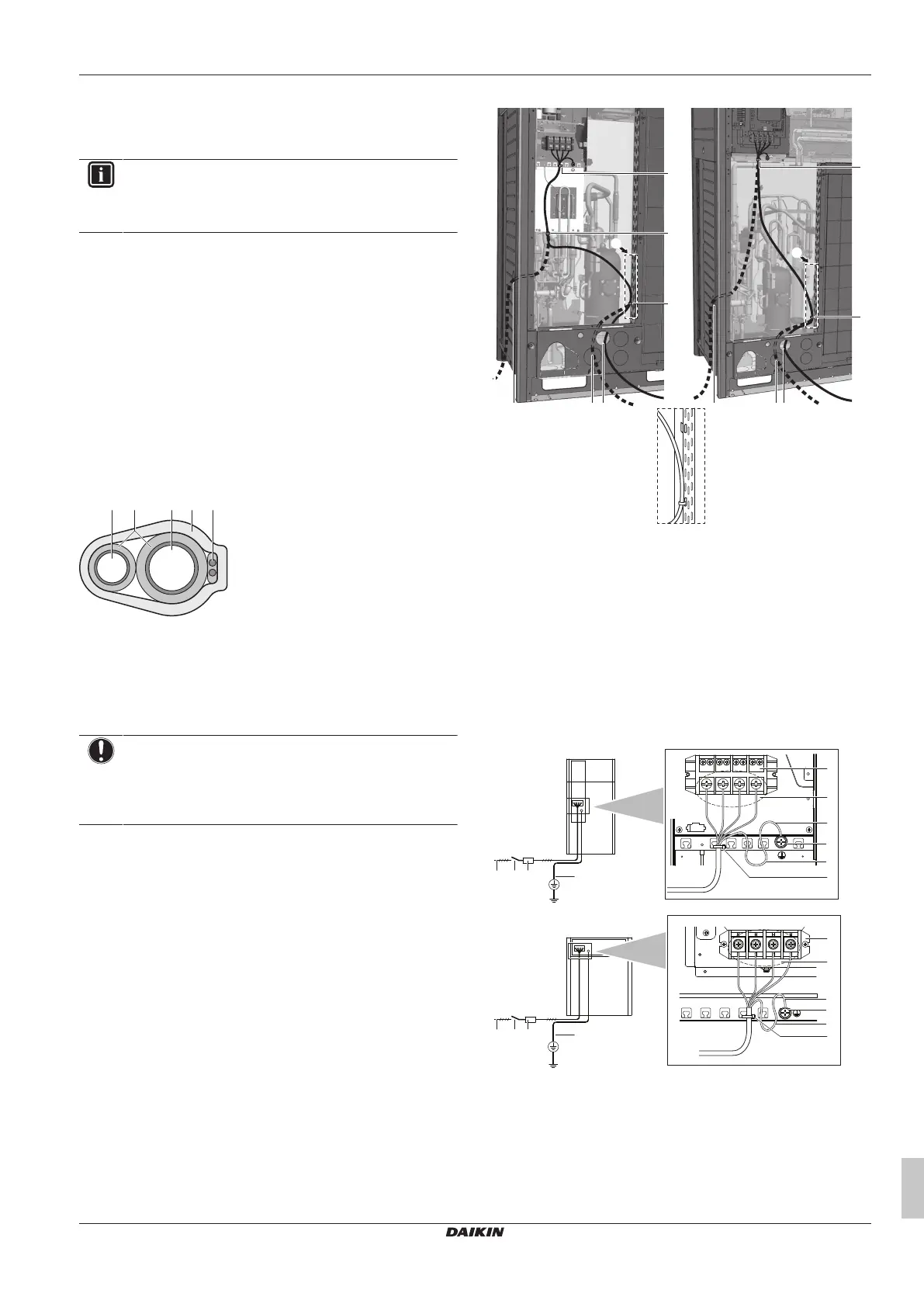
b Unit B (slave outdoor unit)
c Unit C (slave outdoor unit)
d Master/slave transmission (Q1/Q2)
e Outdoor/indoor transmission (F1/F2)
f Outdoor unit/other system transmission (F1/F2)
INFORMATION
U-series units cannot share the same refrigerant circuit
with T-series units. However, electrically, U-series units
and T-series units can be connected via F1/F2.
▪ The interconnecting wiring between the outdoor units in the same
piping system must be connected to the Q1/Q2 (Out Multi)
terminals. Connecting the wires to the F1/F2 terminals results in
system malfunction.
▪ The wiring for the other systems must be connected to the F1/F2
(Out-Out) terminals of the PCB in the outdoor unit to which the
interconnecting wiring for the indoor units is connected.
▪ The base unit is the outdoor unit to which the interconnecting
wiring for the indoor units is connected.
15.6 To finish the transmission wiring
After installing the transmission wires inside the unit, wrap them
along with the on-site refrigerant pipes using finishing tape, as
shown in figure below.
a Liquid pipe
b Gas pipe
c Insulator
d Transmission wiring (F1/F2)
e Finishing tape
15.7 To route and fix the power supply
NOTICE
When routing earth wires, secure clearance of 25 mm or
more away from compressor lead wires. Failure to observe
this instruction properly may adversely affect correct
operation of other units connected to the same earth.
The power supply wiring can be routed from the front and left side.
Fix it to the lower mounting hole.
c
X1M
abac
d
X1M
b
8~12 HP 14~20 HP
A
A
A
d
d
d
d
a Power supply (possibility 1)
(a)
b Power supply (possibility 2)
(a)
c Power supply (possibility 3)
(a)
. Use conduit.
d Tie wrap
(a) Knockout hole has to be removed. Close the hole to avoid
small animals or dirt from entering.
15.8 To connect the power supply
The power supply MUST be clamped to the plastic bracket using
field supplied clamp material to prevent external force being applied
to the terminal. The green and yellow striped wire MUST be used for
earthing only.
a Power supply (380~415 V, 3N~50Hz)
b Fuse
c Earth leakage protector
d Earth wire
e Power supply terminal block
f Connect each power wire: RED to L1, WHT to L2, BLK to
L3 and BLU to N
g Earth wire (GRN/YLW)
h Tie wrap
i Cup washer

 Loading...