32 | RS8EU702 |
DI1
Digital input signal.
The dened function is active when the input is short-circuited/
opened. The function is dened in o02.
DI2
Digital input signal.
The dened function is active when the input is short-circuited/
opened. The function is dened in o37.
S3, S4, S5, S3B, S5B
Pt 1000 ohm sensor or PTC 1000 ohm sensor. All have to be of
the same type.
S6,S6B
Pt 1000 ohm sensor
S3, air sensor, placed in the warm air before the evaporator
S4, air sensor, placed in the cold air after the evaporator
(the need for either S3 or S4 can be deselected in the
conguration)
S5, defrost sensor, placed on the evaporator
S6, product sensor
EKA Display
If there is be external reading/operation of the controller, display
type EKA 163B or EKA 164B can be connected.
RS485 (terminal 51, 52, 53)
For data communication, but only if a data communication
module is inserted in the controller. The module can be a LON
RS485, DANBUSS or a MODBUS.
Terminal 51 = screen
Terminal 52 = A (A+)
Terminal 53 = B (B-)
(For LON RS485 and gateway type AKA 245 the gateway must be
version 6.20 or higher.)
RJ45
For data communication, but only if a TCP/IP module is inserted in
the controller. (OEM)
MODBUS
For data communication.
Terminal 56 = screen
Terminal 57 = A+
Terminal 58 = B-
(Alternatively the terminals can be connected to an external
display type EKA 163A or 164A, but then they cannot be used
for data communication. Any data communication must then be
carried out by one of the other methods.)
Supply voltage
230 V a.c.
DO1
Connection of solenoid valve or relay for compressor. The coil
must be a 230 V a.c. coil.
DO2
Alarm
There is a connection between terminal 7 and 8 in alarm
situations and when the controller is without power.
Night blind
There is connection between terminal 7 and 9 when the night
blind is up/down.
Suction line valve
There is connection between terminal 7 and 9 when the
suction line must be open.
Rail heat
There is connection between terminal 7 and 8 when the
function must be active.
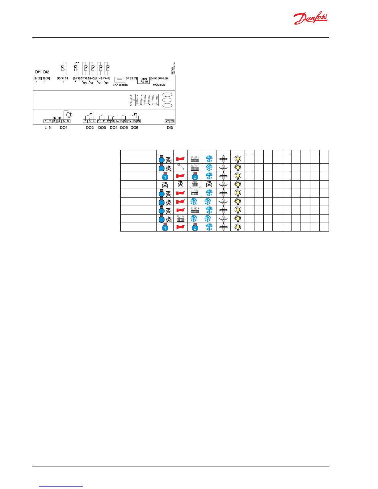
Connections
Overview of outputs and
applications.
See also electrical diagrams earlier
in the manual
Application DO1 DO2 DO3 DO4 DO5 DO6 DI1 DI2 DI3 AI1 AI2 AI3 AI4 AI5 AI6
1
/
• • •
S3 S4 S5 S6
2
/
Blinds
• • •
S3 S4 S5 S6
3
• • •
S3 S4 S5 S6
4
suction
hotgas
• • •
S3 S4 S5 S6
5
/
heat
• • •
S3 S4 S5 S6
6
/
B A
• • •
S3B S5B S3A S4 S5 S6
7
/
• • •
S3B S6B S3A S4 S5 S6A
8
/
B A
• • •
S3B S5B S3A S4 S5 S6
9
• • •
S3 S4 S5 S6

 Loading...