14 Manual RS8EJ302 © Danfoss 05-2010 AK-PC 530
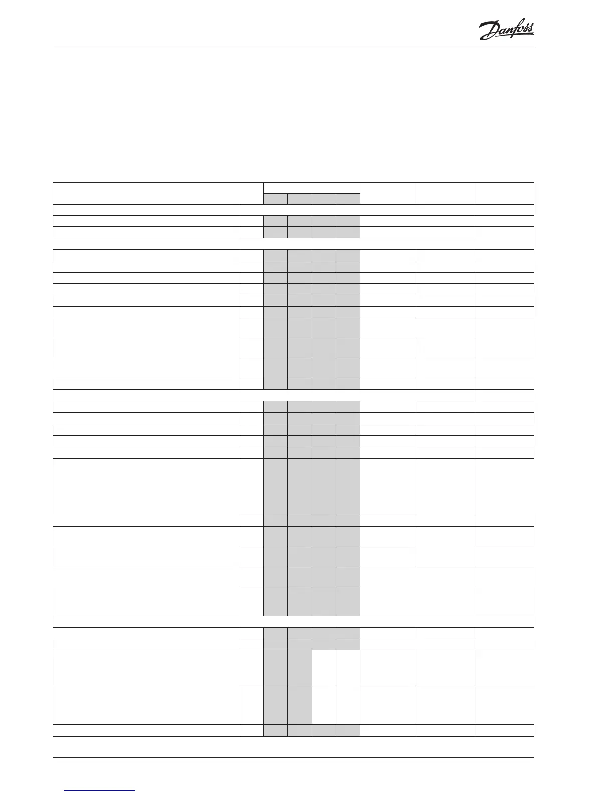
Menu survey
To be continued
SW: 1.3x
Sequence
1. o61 must be set as the rst parameter. This parameter determines which of the four operating interfaces (application mode) are
activated. This must be set via the display keys. It cannot be set via data communication. (Active functions are shown below in shaded
elds.)
2. Quick- start
To get the system up and running quickly so that cooling can be commenced, start it by setting the following parameters (these pa-
rameters can only be set when the regulation is stopped, r12=0):
r23, r28 and then either (c08, c09 and c16) or (c17 to 28) – continue with c29, o06, o30, o75, o76, o81 and nally r12=1.
3. Once the regulation is under way, you can go through the other parameters and adjust them in situ.
Function
Para-
meter
o61 =
Min. Max. Factory
setting
1 2 3 4
Normal display
Shows P0 in EKA 165 (display with buttons) - °C P °C P °C / bar
Shows Pc in EKA 163 - °C P °C P °C / bar
P0 reference
Neutral zone r01 0.1°C / 0.1 bar 20°C /5.0 bar 4.0°C / 0.4 bar
Correction of signal from P0 sensor r04 -50°C /-5.0 bar 50°C / 5.0 bar 0.0
Select view; SI or US. 0=SI (bar /°C), 1=US (Psig /°F)
r05 0 1 0
Start/Stop of regulation
r12 OFF ON OFF
Reference oset for P0 (see also r27) r13 -50°C / -5.0 bar 50°C / 5.0 bar 0.0
Set regulation setpoint for P0 r23 -99°C / -1 bar 30°C / 60.0 bar 0.0°C / 3.5 bar
Shows total P0 reference
( r23 + various displacements)
r24 °C / bar
Limitation: P0 reference max. value
(also applies to regulation with reference displacement)
r25 -99°C / -1.0 bar 30°C / 60.0 bar 30.0°C / 40.0 bar
Limitation: P0 referencen min. value
(also applies to regulation with reference displacement)
r26 -99°C / -1.0 bar 30°C / 40.0 bar -99.9°C / -1.0 bar
Displacement of P0 (ON=active “r13”) r27 OFF ON OFF
Pc reference
Set regulation setpoint for Pc r28 -25°C / 0.0 bar 75°C / 110.0 bar 35°C / 15.0 bar
Shows total Pc reference r29 °C / bar
Limitation: Pc referencen max. value r30 -99.9°C / -0.0 bar 99.9°C/130.0bar 55.0°C / 60.0 bar
Limitation: Pc referencen min. value r31 -99.9°C / 0.0 bar 99.9°C/ 60.0bar -99.9°C / 0.0 bar
Correction of signal from Pc sensor r32 -50°C / -5.0 bar 50°C / 5.0 bar 0.0
Pc reference variation.1 and 2 are PI-regulation
1: Fixed reference. “r28” is used
2: Variable reference. Outdoor temperature (Sc3) included
in the reference
3: As 1, but with P-regulation (Xp-band)
4: As 2, but with P-regulation (Xp-band)
r33 1 4 1
Reference oset for Pc r34 -50°C / -5.0 bar 50°C / 5.0 bar 0.0
The mean temperature dierence across the condenser at
maximum load (dim tm K)
r35 3.0 50.0 10.0
The mean temperature dierence across the condenser at
the lowest relevant compressor capacity (min tm K)
r56 3.0 50.0 8.0
This is where you can see the actual pressure (P0) that is
being measured by the pressure transmitter.
r57 °C / bar
This is where you can see the actual pressure (T0) that is
part of the regulation. From the sensor which is dened
in “o81”
r58 °C
Capacity
Min. ON time for relays c01 0 min 30 min. 0
Min. time period between cutins of same relay c07 0 min. 60 min 4
Denition of regulation mode
1: Sequential (step mode / FILO)
2: Cyclic (step mode / FIFO)
3: Binary and cyclic
c08 1 3 1
If a regulation mode with unloaders is selected, the relay
must be dened to:
0: Cut in when more capacity is required
1: Cut out when more capacity is required
c09 0 1 0
Regulation parameter for + Zone c10 0.1 K / 0.1 bar 20 K / 2.0 bar 4.0 / 0.4 bar

 Loading...


