AK-PC 530 Manual RS8EJ302 © Danfoss 05-2010 3
Sequential (rst in - last out)
The relays are here cut in in sequence – rst relay number 1, then
2, etc.
Cutout takes place in the opposite sequence, i.e. the last cut-in
relay will be cut out rst.
Cyclic (rst in - rst out)
The relays are coupled here so that the operating time of the
individual relays will become equalised.
At each cutin the regulation scans the individual relays’ timer,
cutting in the relay with least time on it.
At each cutout a similar thing happens. Here the relay is cut out
that has most hours on the timer.
If capacity regulation is carried out on two compressors with one
unloader each, the following function can be used:
Relays 1 and 3 are connected to the compressor motor.
Relays 2 and 4 are connected to the unloaders.
Relays 1 and 3 will operate in such a way that the operating time
for the two relays will become equalised.
Rx = random relay
h = number of hours
C = compressor, L = Unloader
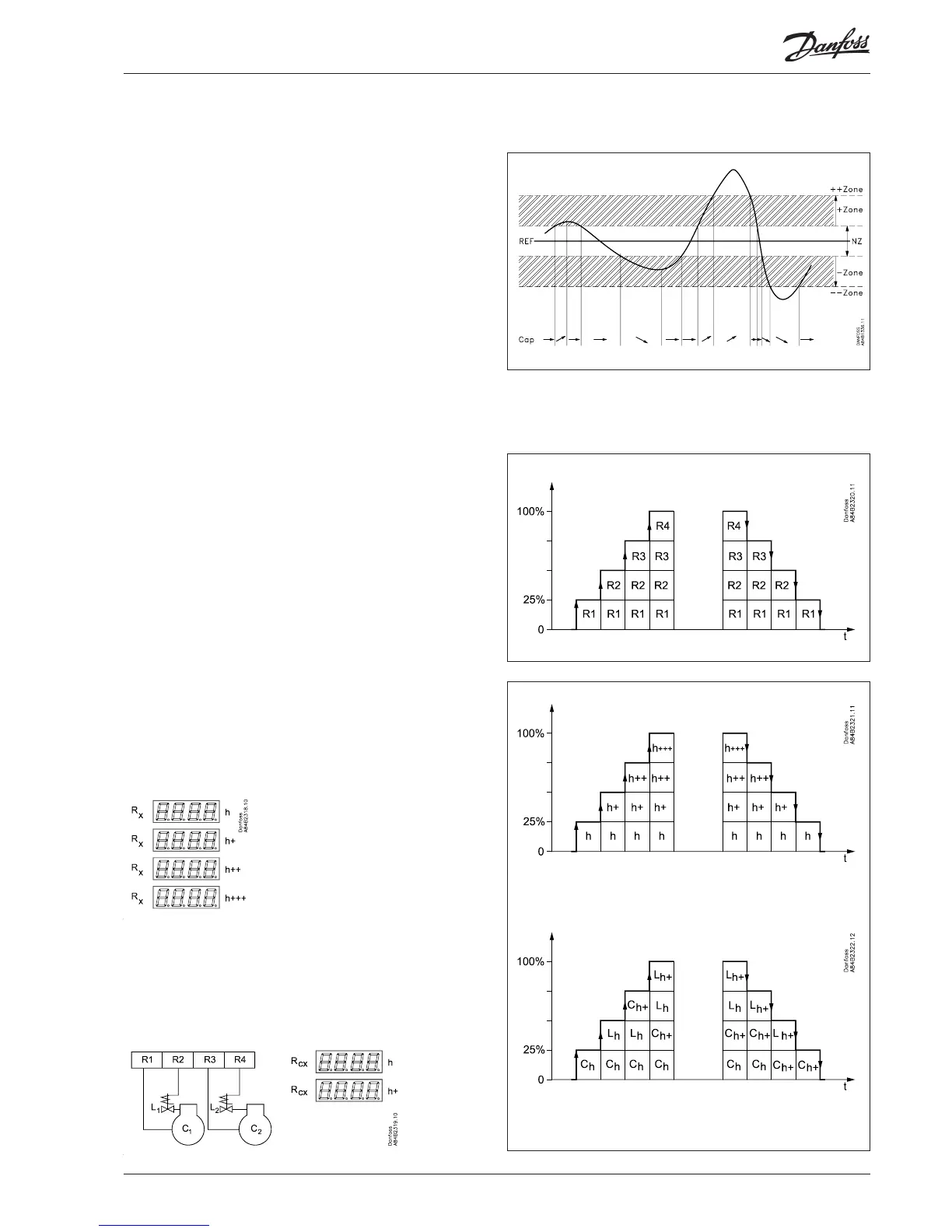
Function
Capacity regulation
The cut-in capacity is controlled by signals from the connected
pressure transmitter/temperature sensor and the set reference.
Outside the reference a neutral zone is set where the capacity will
neither be cut in nor out.
Outside the neutral zone (in the hatched areas named +zone and
-zone) the capacity will be cut in or out if the regulation registers a
change of pressure “away” from the neutral zone. Cutin and cutout
will take place with the set time delays.
If the pressure however “approaches” the neutral zone, the con-
troller will make no changes of the cut-in capacity.
If regulation takes place outside the hatched area (named ++zone
and --zone), changes of the cut-in capacity will occur somewhat
faster than if it were in the hatched area.
Cutin of steps can be dened for either sequential, cyclic, binary or
"mix & match" operation.

 Loading...


