18 Manual RS8EJ302 © Danfoss 05-2010 AK-PC 530
Necessary connections
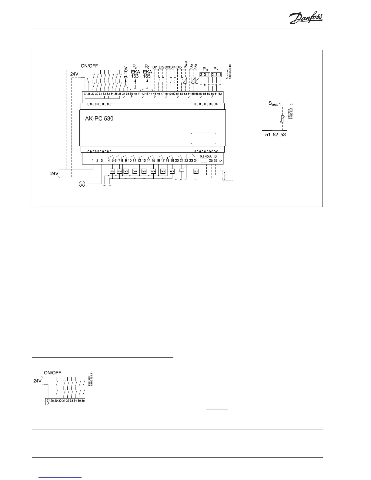
Terminals:
1-2 Supply voltage 24 V a.c.
4- 19 Relay outputs for either compressors, unloaders or fan mo-
tors
22-24 Alarm relay *
There is connection between 22 and 24 in alarm situa tions
and when the controller is dead
27-28 24 V signal to start / stop of regulation
27-29 24 V signal from the safety circuit DO 1
27-30 24 V signal from the safety circuit DO 2
27-31 24 V signal from the safety circuit DO 3
27-32 24 V signal from the safety circuit DO 4
27-33 24 V signal from the safety circuit DO 5
27-34 24 V signal from the safety circuit DO 6
27-35 24 V signal from the safety circuit DO 7
27-36 24 V signal from the safety circuit DO 8
57-59 Suction pressure. Voltage signal from AKS 32R **
60-62 Condenser pressure. Voltage signal from AKS 32R **
Connections
Application dependent connections
20-21 AKD start/stop *
The relay cutin when the frequency converter have to
start.
37-38 Voltage signal to external condenser control
(see settings page 12)
39-41 Possibility of connecting an external display type EKA 163
or display of Pc
42-44 Possibility of connecting an external display type EKA 163
for display of P0, or EKA 165 for operation and display of
P0
45-46 DI1 - Contact function for alarm signal
45-47 DI2 - Contact function for alarm signal
48-49 DI3 - Contact function for alarm signal
48-50 DI4 - Contact function for displacement of the suction
pressure reference or for alarm signal.
51-52 DI5 - Contact function for displacement of the condenser
pressure reference or for alarm signal.
51-53 Separate sensor Saux1. Sensor signal from AKS 11, AKS 12
or EKS 111
54-55 Out temperature (Sc3). Sensor signal from AKS 11, AKS 12
or EKS 111 (mounted if r33 =2 or 4)
54-56 Air temperature at condenser outlet. Sensor signal from
AKS 11, AKS 12 or EKS 111
Data communication
25-26 Mount only, if a data communication module has been
mounted.
For ethernet communication the plug connection RJ45
must be used. (LON FTT10 can also be connected in this
way.
It is important that the installation of the data communi-
cation cable be done correctly. Cf. separate literature No.
RC8AC.
All inputs are low-voltage.
All relay outputs may be
high-voltage.
If an output is used for an unloader it
is not necessary to wire the belonging
safety circuit.
Ex. with an unloader on DO2 a connec-
tion on terminal 30 can be left out
*)
Relays DO9 and DO10 may in special cases be recongurated so that they can be
used as fan relays. See also page 9.
Unloader
**)
• If the controller has to control only the compressor or the fans, respectively Pc and P0
sensor can be dispensed
• In brine systems temperature measurement at terminals 57-58 and 60-61 may be
used instead of pressure measurement with AKS 32R. See also o06.
P0/Pc: AKS 32R:
1 = Black = +
2 = Blue = -
3 = Brown = s
Compressor control
with temperature
o06 = 0
o81 = 1
Other combinations: see page 21

 Loading...


