AK-PC 530 Manual RS8EJ302 © Danfoss 05-2010 19
Data Ordering
Installation considerations
Accidental damage, poor installation, or site conditions, can give
rise to malfunctions of the control system, and ultimately lead to a
plant breakdown.
Every possible safeguard is incorporated into our products to
prevent this. However, a wrong installation, for example, could still
present problems. Electronic controls are no substitute for normal,
good engineering practice.
Danfoss wil not be responsible for any goods, or plant compo-
nents, damaged as a result of the above defects. It is the installer's
responsibility to check the installation thoroughly, and to t the
necessary safety devices.
Special reference is made to the necessity of signals to the
controller when the compressor is stopped and to the need of
liquid receivers before the compressors.
Your local Danfoss agent will be pleased to assist with further
advice, etc.
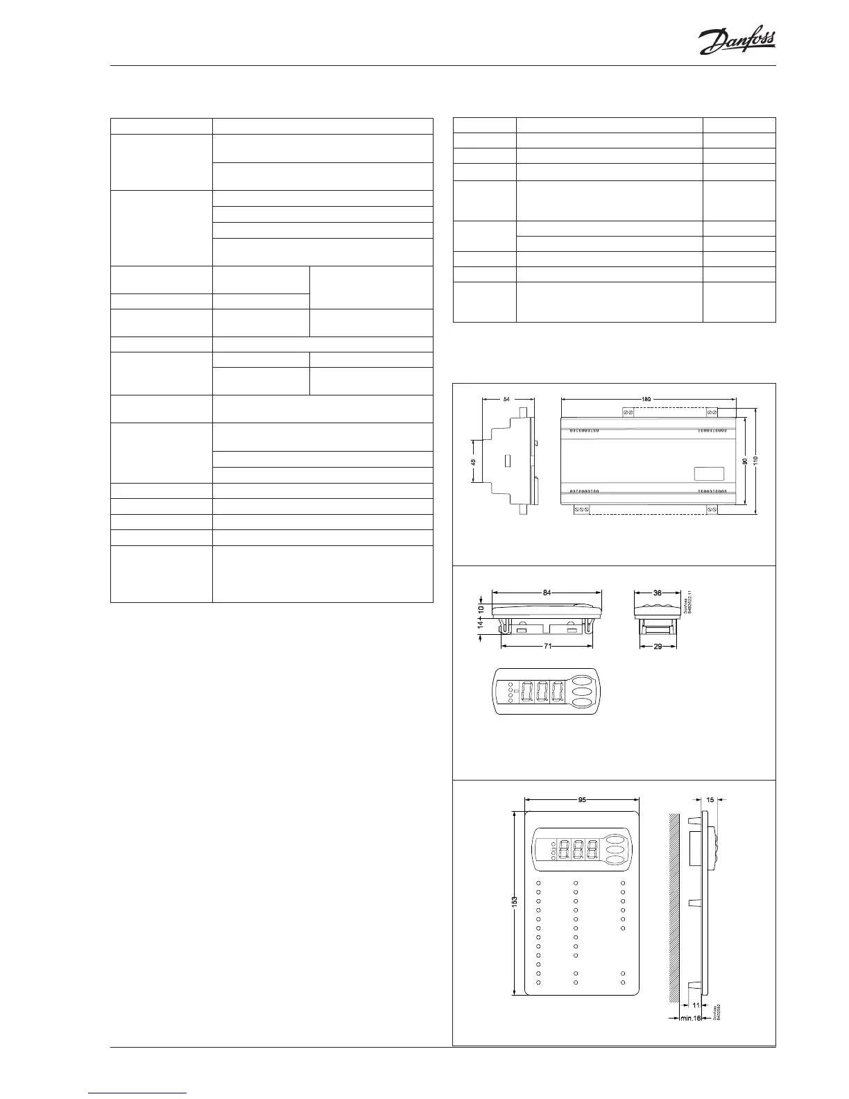
Montage
Supply voltage 24 V a.c. +/-15% 50/60 Hz, 5 VA
Input signal
2 pcs. Pressure transmitters type AKS 32R
(temperature sensor in brine systems)
3 pcs. temperature sensor input for PT 1000
ohm/0°C or PTC 1000 ohm/25°C
Digitale input from
contact function.
1 pcs. for Start/stop of regulation
8 pcs. for monitoring of safety circuits
3 pcs. for alarm function
2 pcs. for alarm function or for displacement of
references
Relay output for
capacity regulation
8 pcs. SPST
AC-1: 3 A (ohmic)
AC-15: 2 A (inductive)
"AKD start/stop" relay 1 pcs. SPST
Alarm relay 1 pcs. SPDT
AC-1: 6 A (ohmic)
AC-15: 3 (inductive)
Voltage output 0-10 V d.c. Max. 5 mA, Ri min. 2.2 kohm
Display outputs
EKA 163 Pc display
EKA 165(164)
Operation, P0 display and
LED
Data communication
Possible to connect a data communication
module
Environments
0 - 55°C, during operation
-40 - 70°C, during transport
20 - 80% Rh, not condensing
No shock inuence / vibrations
Enclosure IP 20
Weight 0.4 kg
Mounting DIN rail or on wall
Terminals max. 2.5 mm
2
multicore
Approvals
EU Low voltage Directive and EMC demands re
CE-marking complied with.
LVD-tested acc. to EN 60730-1 and EN 60730-2-9
EMC-tested acc. to EN61000-6-2 and 3
Pressure transmitter / temperature sensor
Please refer to catalogue RK0YG...
Type Function Code no.
AK-PC 530 Capacity controller 084B8007
EKA 163B Display unit 084B8574
EKA 164B Display unit with operation buttons 084B8575
EKA 165
Display unit with operation buttons
and light-emitting diodes for input and
output
084B8573
Cable for display unit 2 m, 1 pcs. 084B7298
Cable for display unit 6 m, 1 pcs. 084B7299
EKA 175 Data communication module, RS 485 084B8579
EKA 178B Data communication module, MOD-bus 084B8571
EKA 174
Data communication module, LON RS
485, with galvanic separation (recom-
mended when output 0-10 V is used)
084B7124

 Loading...


