Device Description
26
3 Device Description
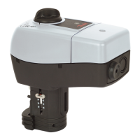
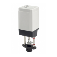
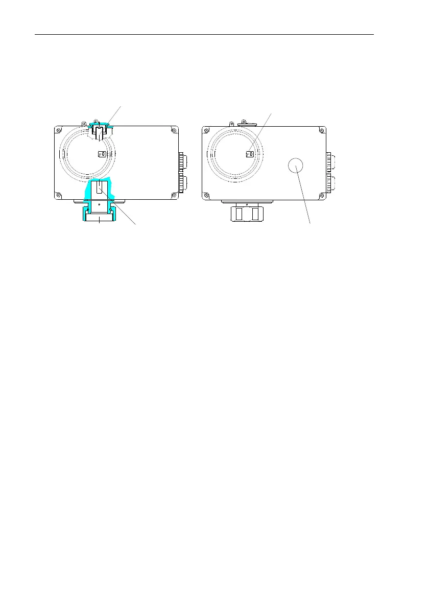
3.1 Construction
3.2 Description
The actuator unit consists of a
spur gear with a synchronous
motor. The transformation of the
rotation movement into an axial
movement of the stem is realized
by means of a gear wheel seg-
ment.
When reaching a defined posi-
tioning force, the actuator is
switched off at its end positions.
The maximum stroke of the
electrical actuator is set in accor-
dance with the valve stroke by
means of the stroke limiting screw.
Positioner
(ISR design)
With this design, the positioning
signal (0(4)−20 mA / 0(2)−10 V)
transmitted by an electrical control
unit is compared with the posi-
tioning stroke signal of a potentio-
meter. A three-position step signal
is then derived from the difference
between these signals and used
to trigger the synchronous motor.
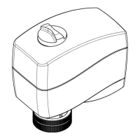
Mechanical Manual Adjustment
For the type AMV(E)210, the
stroke can be adjusted by means
of an external rotary knob. With
the type AMV(E)213, this can be
done after having removed the
housing cover by means of a
hexagon socket screw key.
End switches
(Additional equipment)
The two voltage-free end switches
automatically switch in the end
positions. There is no adjustment
required.
Stroke limiting
Stroke indicator
screw
Stem
Mechanical
manual adjustment
AMV(E)210
 Loading...