Adjustments AME210, AME213
37
7 Adjustments AME210, AME213
Prior to commissioning, the input and output signals must be adjusted and
the end positions must be aligned.
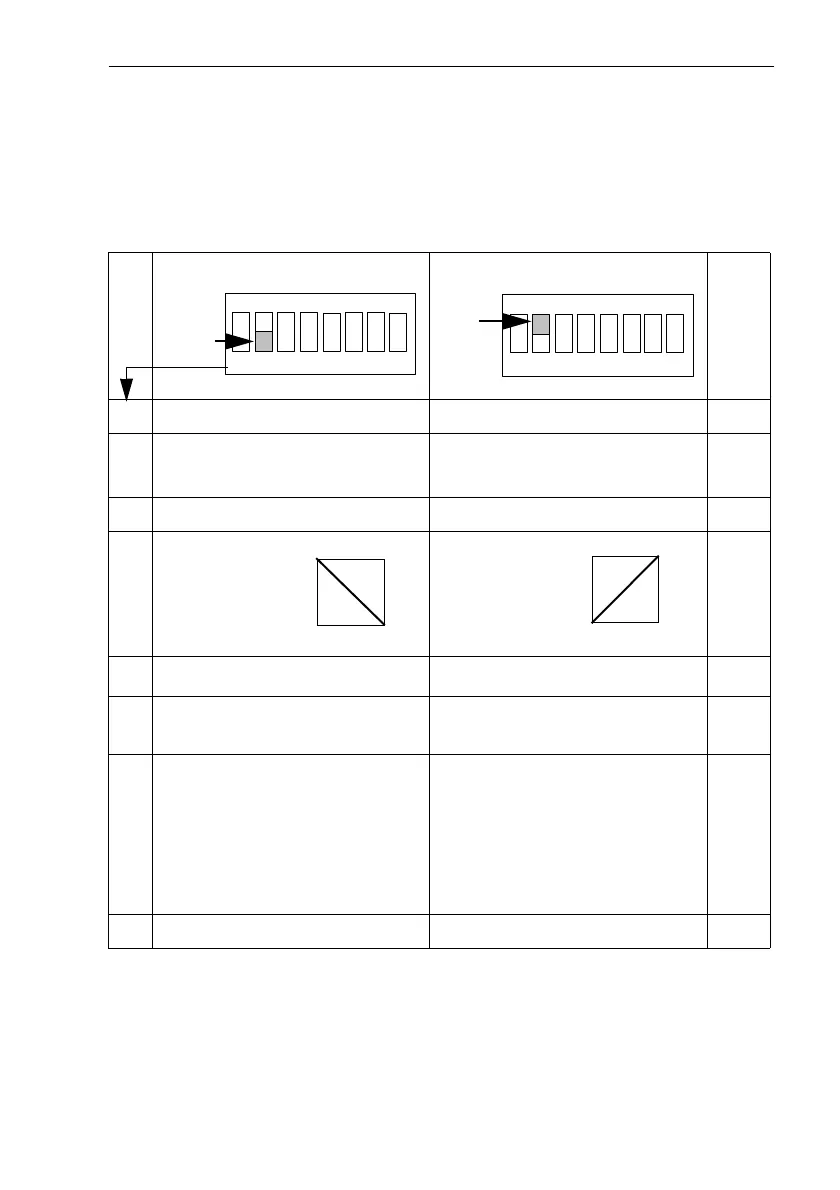
7.1 Overview DIP switch settings
1)
During control operation, it is absolutely necessary to set switch to
automatic.
The switch positions 1, 6, 7, 8 have no influence on normal control
operation.
see section
1 Without function Without function
2 Input signal 4 - 20 mA
2 - 10 V
Input signal 0 - 20 mA
0 - 10 V
7.2
3 Output signal 2 - 10 V Output signal 0 - 10 V 7.3
47.4
5
Automatic operation
1)
Manual operation 8.3
6 Manual operation:
Extend stem
Manual operation:
Retract stem
8.3
7 There is no new alignment of
the end positions
When switching on the po-
wer supply, the stem is ex-
tended until the valve is
closed,
End position „Valve closed“
is re-aligned.
-
8 Fault indicator ON Fault indicator OFF 9.3
1 2 3 4 5 6 7 8
ON
OFF
1 2 3 4 5 6 7 8
ON
ON
0 Hub 100 %
0(2, 4)
20 mA
10 V
Inverse operation
0 Hub 100 %
0(2, 4)
20 mA
10 V
Normal operation
 Loading...