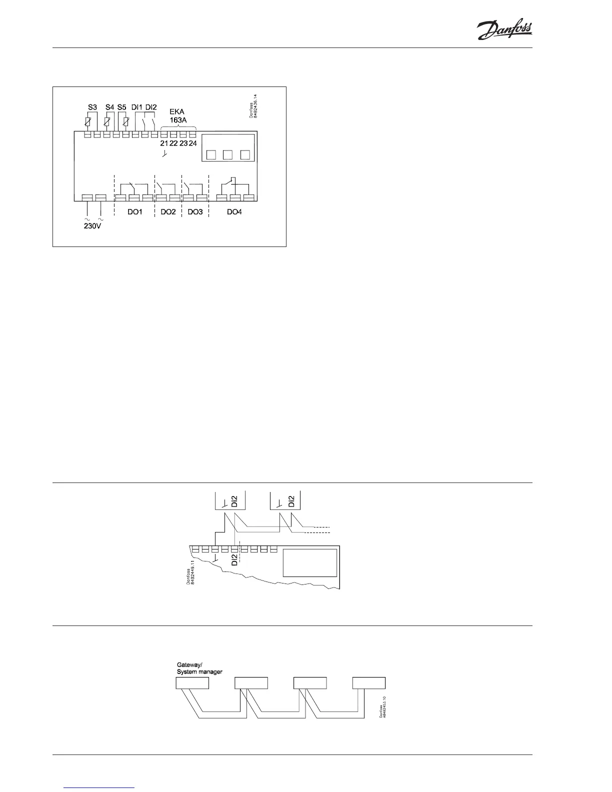
Connections
Power supply
230 V a.c. (115 V version available)
Sensors
S3 and S4 are thermostat sensors.
A setting determines whether S3 or S4 or both of them are to be
used.
S5 is a defrost sensor and is used if defrost has to be stopped
based on temperature.
Digital On/Off signals
A cut-in input will activate a function. The possible functions are
described in menus o02 and o37.
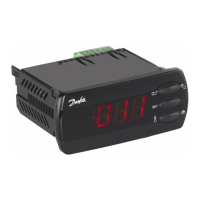
External display
Connection of display type EKA 163A.
Coordinated defrost via
data communication
Coordinated defrost via
cable connections
The following controllers can be connected
up in this way:
EKC 204A, EKC 202D
Refrigeration is resumed when all
controllers have “released” the signal for
defrost.
Relays
The general uses are mentioned here. See also page 6 where the
dierent applications are shown.
DO1: Refrigeration. The relay will cut in when the controller de-
mands refrigeration
DO2: Defrost. The relay will cut in when defrost is in progress
DO3: Fans
The relay will cut in when the fans have to operate
DO4: For either alarm, rail heat or light
Alarm: Cf. diagram. The relay is cut in during normal opera-
tion and cuts out in alarm situations and when the controller
is dead (de-energised)
Rail heat: The relay cuts in when rail heat is to operate
Light: The relay cuts in when the light has to be switched on
Data communication
The controller is available in several versions where data com-
munication can be carried out with one of the following systems:
MOD-bus or LON-RS485.
If data communication is used, it is important that the installation
of the data communication cable is performed correctly.
See separate literature No. RC8AC…
Electric noise
Cables for sensors, DI inputs and data communication must be
kept separate from other electric cables:
- Use separate cable trays
- Keep a distance between cables of at least 10 cm
- Long cables at the DI input should be avoided
(115 V a.c.)

 Loading...