Applications
Here is a survey of the controller’s eld of application.
A setting will dene the relay outputs so that the controller’s inter-
face will be targeted the chosen application.
On page 17 you can see the relevant settings for the respective
wiring diagrams.
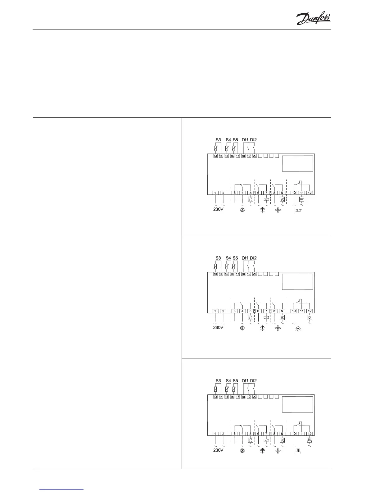
Refrigeration control with one compressor
The functions are adapted to small refrigeration systems which
may be either refrigeration appliances or coldrooms.
The three relays can control the refrigeration, the defrost and the
fans, and the fourth relay can be used for either alarm function,
light control or rail heat control.
• The alarm function can be linked up with a contact function
from a door switch. If the door remains open longer than al-
lowed an alarm is triggered.
• The light control can also be linked up with a contact function
from a door switch. An open door will switch on the light and
it will remain lit for two minutes after the door has been closed
again.
• The rail heat function can be used in refrigeration or freezing
appliances or on the door’s heating element for frostrooms.
The fans can be stopped during defrost and they may also follow
a door switch’s open/close situation.
There are several other functions for the alarm function as well
as the light control, rail heat control and fans. Please refer to the
respective settings.
1
2
3
S3 and S4 are temperature sensors. The application will deter-
mine whether either one or the other or both sensors are to be
used. S3 is placed in the air ow before the evaporator. S4 after
the evaporator.
A percentage setting will determine according to what the
control is to be based. S5 is a defrost sensor and is placed on the
evaporator.
DI1 and DI2 are contact functions that can be used for one of the
following functions: door function, alarm function, defrost start,
external main switch, night operation, change of thermostat ref-
erence, appliance cleaning, forced refrigeration or coordinated
defrost. See the functions in settings o02 and o37.

 Loading...