10 Manual RS8FM602 © Danfoss 02-2016 EKC 326A
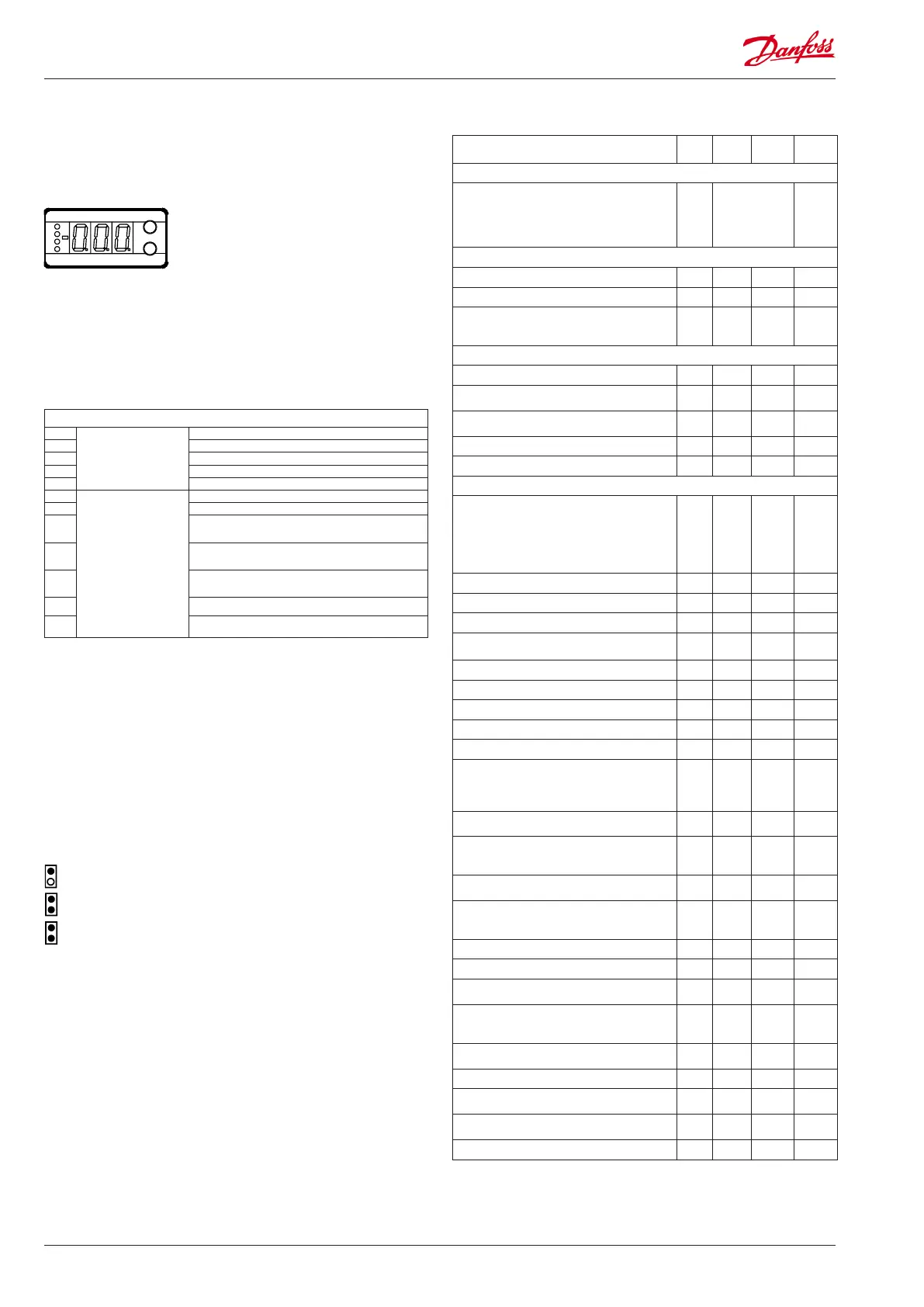
Light-emitting diodes (LED) on front panel
The four LED’s will ash, if there is an error in the regulation.
In this situation you can upload the error code on the display and
cancel the alarm by giving the uppermost button a brief push.
The controller can give the following messages:
E1
Error message
Fault in controller
E15 Cut-out Sgc sensor
E16 Short circuited Sgc sensor
E20 Fault on the signal from Pgc
E39 Fault on the signal from Prec
A43
Alarm message
Step motor error. Output or phase
A45 Regulation stopped. Main switch r12 = o
A82
The Pgc gas pressure measured is higher than the
maximum limit for n69
A83
The Pgc gas pressure measured is lower than Pgc
min (A65)
A84
The receiver pressure measured is lower than "n71"
minus "n72"
A94 Pgc alarm limit "A66" is exceeded
A95 Prec alarm limit "A67" is exceeded
Display
The values will be shown with three digits.
Temperature are to be shown in °C and pressure in bar.
Operation Menu survey
The buttons
When you want to change a setting, the two buttons will give you
a higher or lower value depending on the button you are push-
ing. But before you change the value, you must have access to the
menu. You obtain this by pushing the upper button for a couple
of seconds - you will then enter the column with parameter codes.
Find the parameter code you want to change and push the two
buttons simultaneously. When you have changed the value, save
the new value by once more pushing the two buttons simultane-
ously.
Gives access to the menu
(or cutout an alarm)
Gives access to changes
Saves a change
Examples of operations
Set a menus
1. Push the upper button until a parameter is shown
2. Push one of the buttons and nd the parameter you want to
change
3. Push both buttons simultaneously until the parameter value is
shown
4. Push one of the buttons and select the new value
5. Push both buttons again to conclude the setting
SW =2.0x
**) The display on the controller can show 3 digits only, but the setting value has 4 digits. Only the
3 most important will be shown. It means fx. 250 will give a setting of 2500.
Function
Para-
meter
Min. Max.
Factory
setting
Normal display
Shows the current pressure after the gas cooler
Pushing both buttons briey will display the
reference
Pushing the bottom button briey will display
Prec.
- bar
Start / stop
Start / stop of regulation r12 OFF (0) On (1) On (1)
Ramp for reference after heat recovery r65 0.1 20 1
Displacement of the Pgc minimum reference
(n89) during heat recovery. (Displacement value
at 10 V)
r68 0 bar 100 bar 0
Alarm Settings
Alarm limit for Pgc Min. A65 0 bar 200 bar 40
Permitted Pgc reference variation
0 = no alarm function (recommended)
A66 0 bar 50 bar 0
Permitted Prec reference variation
0 = no alarm function (recommended)
A67 0 bar 50 bar 0
Delay time for 'A94' Pgc reference alarm A68 5 min. 360 min 15
Delay time for 'A95' Prec reference alarm A69 5 min. 360 min 15
Regulating parameters
Actuator type for receiver control
0=ETS12,5/25 / CCM10/20,
1=ETS50 / CCM30, 2=ETS100 / CCM40,
3=ETS250, 4=ETS400,
5=User dened (set: n37 and n38)
6=CCMT2/4/8
n03 0 6 0
P: Amplication factor Kp n04 0.5 20 2.0
I: Integration time Tn n05 10 s 600 s 75
Max. opening degree. of the valve n32 0 100 100
Number of steps from 0-100% opening degree
(x10) **
n37 0 500 262
Number of steps per second n38 0 300 250
Max. permitted receiver pressure, Prec n58 10 bar 200 bar 60
P-belt beyond PrecMax for valve to close n59 0 bar 60 bar 0
P: Amplication factor Kp for receiver n60 0.5 20 5
I: Integration time Tn for receiver n61 10 600 75
The gas cooler’s max. pressure
This is where you set the maximum pressure per-
mitted in the gas cooler. If the pressure reaches
this value, the valve is fully open.
n69 7 200 90
P-band under n69, so the valve is fully open if
the pressure is n69.
n70 0 60 5
Min. pressure in the receiver
This function is only used if the pressure trans-
mitter Prec is mounted.
n71 7 60 30
P-band to force open the valve if the receiver
pressure is too low
n72 0 60 3
Subcooling is required to be regulated accord-
ing to temperature
Set the desired subcooling in K.
n79 1 K 30 K 1
The gas cooler’s min. pressure n81 7 200 bar 45
Min. permissible opening degree for ICMTS n87 0 100% 0
Extra capacity when the contact is closed.
(The Pgc reference is increased with this value)
n88 0 bar 200 bar 0
Minimum permitted Pgc reference during heat
recovery (AI > 2 V). The value can be increased
further using the r68 function.
n89 7 bar 200 bar 7
Do you require receiver pressure control: O=no,
On=yes
n90 O On On
Prec. reference for receiver pressure control n91 7 bar 200 bar 35
Receiver pressure control. Maximum opening
degree for ETS
n92 0% 100% 100
Receiver pressure control. Smallest opening
degree for ETS
n93 0% 100% 0
Dene the reference curve point at 100 bar. n99 35°C 55°C 39

 Loading...