EKC 326A Manual RS8FM602 © Danfoss 02-2016 11
Necessary connections
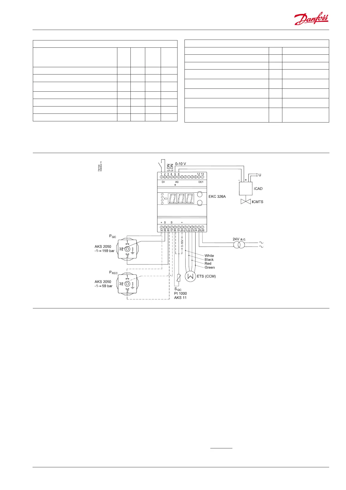
Terminals:
25-26 Supply voltage 24 V a.c.
18-19 Pt 1000 sensor at gas cooler outlet (S
gc
)
14,15,16 Pressure transmitter AKS 2050, -1 to 159 bar
To register the correct pressure it must be mounted as
close as possible to the gas cooler.
5-6 Voltage output to control the ICMTS valve.
Connections
Application dependent connections
Terminals:
1-2 DI-input to either:
External main switch (see o02 and r12)
OR
Contact function for increasing capacity (optimised COP
operation stopped). (see o02)
Open connection = optimised COP operation
Closed connection = extra capacity.
12-13 Alarm relay
There is connection between 12 and 13 in alarm situa tions
14,16,17 Optional. A pressure transmitter can be connected so
that the pressure in the receiver can be monitored. The
pressure transmitter must be an AKS 2050, -1 to 59 bar.
21-24 If receiver pressure is to be controlled, a CCM or ETS valve
should be connected.
18-20 Heat recovery. A voltage signal between 2 and 10 V will
increase the gas pressure reference.
3-4 Data communication
Mount only, if a data communication module has been
mounted.
It is important that the installation of the data communi-
cation cable be done correctly. Cf. separate literature No.
RC8AC...
Factory setting
If you need to return to the factory-set values, it can be done in this way:
- Cut out the supply voltage to the controller
- Keep both buttons depressed at the same time as you recon nect the supply voltage
0 V = valve closed
10 V = valve open
Cable connection
060G1034
14 = black
15 = brown
16 = blue
AKS 11: Max. 100°C
AKS 21: Max. 180°C
*) This setting will only be possible if a data communication module has been installed in the
controller.
See also next page
Miscellaneous
Digital input signal - DI
0: The input is not used
1: External main switch
2: additional cooling capacity
o02 0 2 0
Controller’s address o03* 0 240 -
ON/OFF switch (service-pin message) o04* - - -
Set supply voltage frequency o12
50Hz
(0)
60 Hz
(1)
0
Pressure transmitter range Pgc - min. o20 -1 bar 5 bar -1
Pressure transmitter range Pgc - max. o21 6 bar 199 bar 159
Pressure transmitter range Prec - min. o47 -1 bar 5 bar -1
Pressure transmitter range Prec - max. o48 6 bar 199 bar 59
Service
Signal on AI the input u07 V
Read status of input DI u10 on/o
Read ETS/CCM valves opening degree u24 %
Calculated reference for regulation (desired pres-
sure in the gas cooler)
U03 bar
The output signal to the ICMTS valve converted
into opening degree
U04 %
The temperature in the gas cooler. Measured
using temperature sensor Sgc.
U05 °C
The pressure in the gas cooler. Measured using
pressure transmitter Pgc.
U06 bar
The pressure in the receiver. Measured using
pressure transmitter Prec, but only if it is
mounted.
U07 bar
High pressure valve
Vhp
Gas bypass valve
Vgbp
8 VA
Important
PGC and Sgc must be mount
-
ed near the gas cooler outlet
to produce a correct signal.

 Loading...