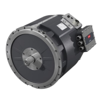
Symbol Explanation
L
F
Length of the machine frame
D
M
Diameter of the ange mounting bore circle.
D
S
Diameter of the mounting shoulder.
D
R
Diameter of the rotor connection interface.
For all dimensions of the electric machine, see the product drawings.
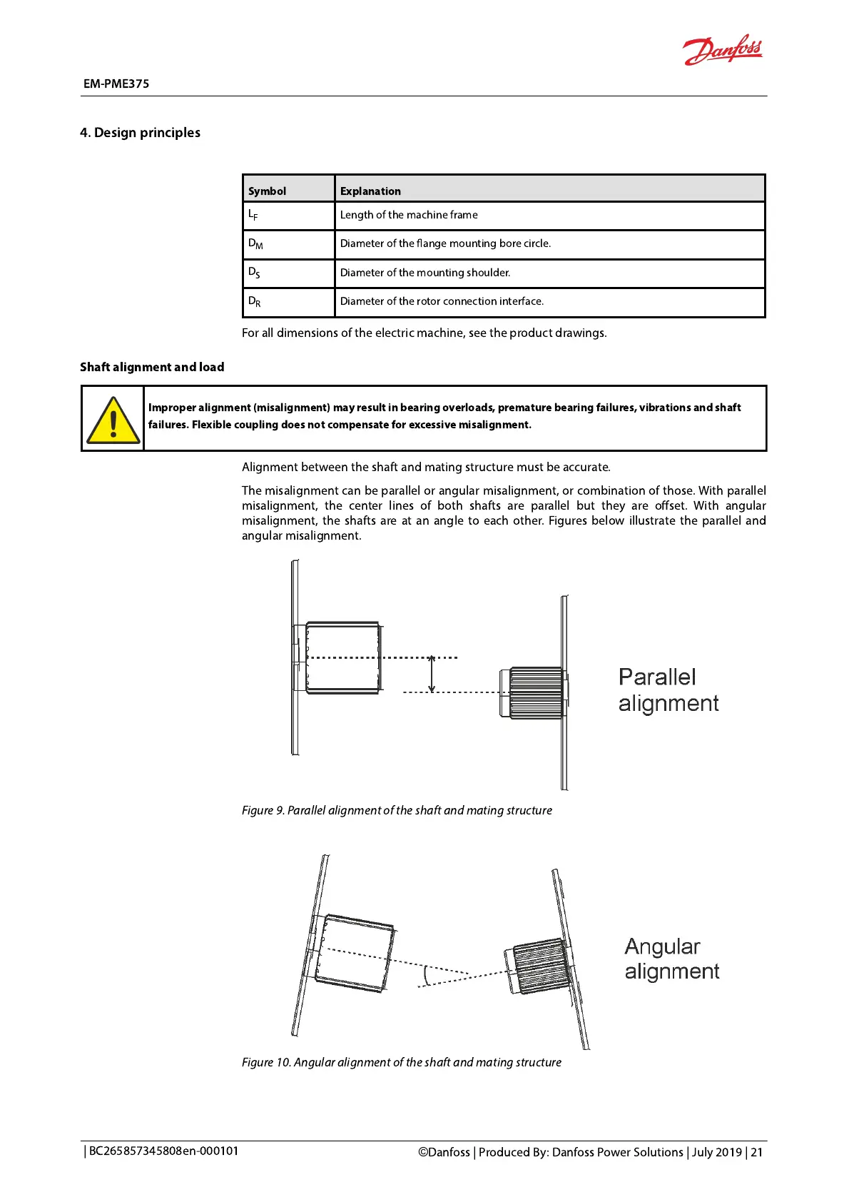
Shaft alignment and load
Improper alignment (misalignment) may result in bearing overloads, premature bearing failures, vibrations and shaft
failures. Flexible coupling does
not compensate for excessive misalignment.
Alignment between the shaft and mating structure must be accurate.
The misalignment can be parallel or angular misalignment, or combination of those. With parallel
misalignment, the center lines of both shafts are parallel but they are offset. With angular
misalignment, the shafts are at an angle to each other. Figures below illustrate the parallel and
angular misalignment.
Figure 9. Parallel alignment of the shaft and mating structure
Figure 10. Angular alignment of the shaft and mating structure
 Loading...