FC 300 Instruction Manual
How to Install
IP 21/IP 4X/ TYPE 1 Enclosure Kit
TheIP21/IP4X/TYPE1enclosurekitconsists
ofasheetmetalpartandaplasticpart. The
sheet m etal part serves as bonding plate for
conduits and is a ttached to the bottom of the
heat sink. The plastic pa rt serves as protection
from live parts on power plugs.
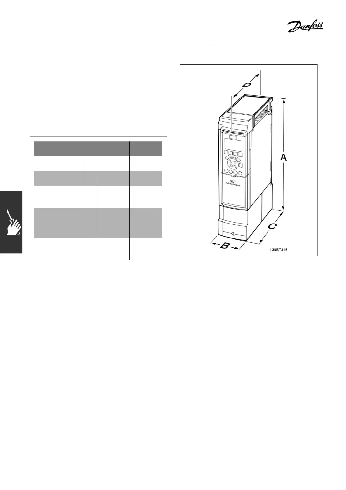
Mechanical
dimensions
Frame
size A2
Frame
size A3
Height A
14.8 in
(375 mm)
14.8 in
(375 mm)
Width B
3.54 in
(90 mm)
5.12 in
(130 mm)
Bottom depth
from back plate
to front
C
7.95 in
(202 mm)
7.95 in
(202 mm)
Top d ept h fr om
back plate
to front (w/o
option)
D
8.15 in
(207 mm)
8.15 in
(207 mm)
Top d ept h fr om
back plate to
front (w/ option)
D
8.74 in
(222 mm)
8.74 in
(222 mm)
Mechanical dimensions of the IP 21/IP 4x/
TYPE 1 enclosure kit
1. Drill holes
in accordance with the m easurements given.
2. You must provide screws suitable for the surface on which you want to mount
the FC 300. Retighten all four screws.
FC 300 IP20
allows side-by-side installation. Because of the need for cooling, there must be a
minimum of 4 in (100 mm) free air passage above and below the FC 300.
14
MG.33.A4.22 - VLT is a registered Danfoss trademark

 Loading...


