3.
3.1.
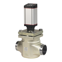
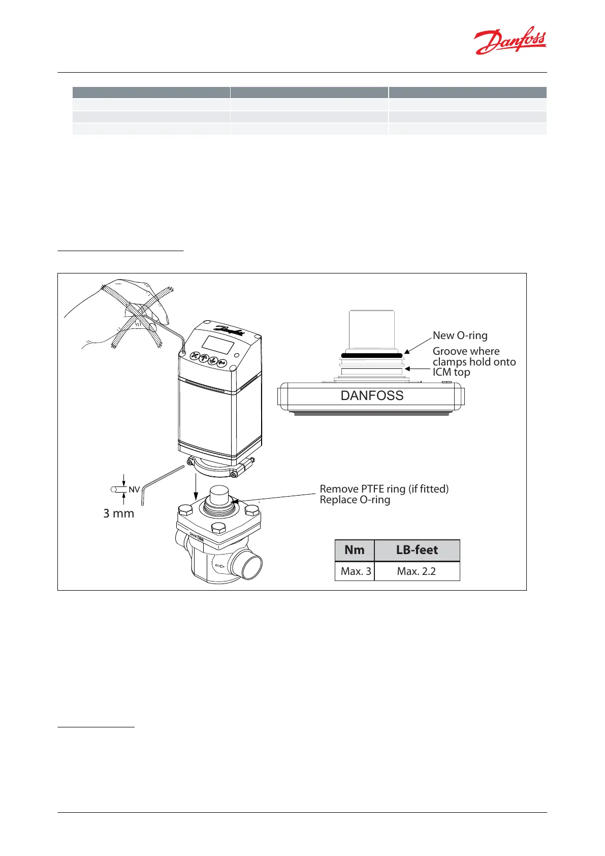
Install the ICAD Motor on the ICM/ICMTS valve:
The ICM/ICMTS valve must not be in its full opened position while the ICAD motor is calibrated with the valve (at a
later step). Therefore, if the opening degree of the ICM/ICMTS valve was changed from the factory setting, it
should be set to an opening degree between 0% and 75% using the manual magnet tool. To easily ensure
correct positioning, turn the manual tool counter-clockwise until it is clear that it cannot be turned any further.
Make sure that the ICM/ICMTS adapter/valve stem and inner ICAD magnets are completely dry and free
from any debris
Mechanical installation
Figure 5: Procedure for ICAD installed on all valves
Nm LB-feet
mm
Groove where
clamps hold onto
ICM top
Remove PTFE ring (if fitted)
Replace O-ring
New O-ring
DANFOSS
Max. 3 Max. 2.2
General procedure for ICAD 600B/ICAD 600B-TS/1200B installed on all valves
• Check that the two socket screws are fully unscrewed counter clockwise with a 3 mm Hexagon key
• If valve is tted with PTFE ring and O-ring, remove both and replace it with O-ring included in ICAD (as instructed
in
Figure 5)
• Mount ICAD by slowly lowering it on top of the valve
• The magnet coupling will drag the valve and ICAD together and in position
• Push ICAD in place
• Fasten valve and ICAD with the two socket set screws using a 3 mm Hexagon key
Electrical data
Supply voltage is galvanically isolated from in-/output. ICAD is a Class III product.
PSUs connected to ICAD must be SELV<100 VA
For UL compliance: PSU must be Class 2 NEC
ICM and ICMTS Motorized Valves with ICAD Actuators
© Danfoss | Climate Solutions | 2024.01 BC465027827472en-000102 | 8
 Loading...