12 RS8FD402 © Danfoss A/S 2014/11 OPTYMA
TM
Control single-phase AK-RC 101
Variables Explanation Value Default
Fd Fan dierential below Fst 0…+10K 2K
LSE Min. limit of set point setting -45...HSE -45°C
HSE Max. limit of set point setting 45... LSE 45°C
tA NO – NC alarm relay switching 0 = activates when alarm is on
1 = deactivates when alarm is on
1
AU Auxiliary/alarm relay control 0 = alarm relay
1 = manual auxiliary relay
controlled via AUX key
2 = automatic auxiliary relay
managed by StA temp. setting
with 2°C dierential
3 = not used
4 = pump-down function (see 5.15)
5 = free voltage contact for
condensing unit (AUX relay and
compressor relay in parallel)
6 = Relay used to control a heating
element in the crankcase.
The relay is on when the
compressor is stopped.
7 = The relay function is cancelled
and data communication is
permitted
0
StA Temp. setting for aux. relay -45…+45°C 0
In1 Man in cold room alarm
Select input INP1 on the board as compressor
protection alarm or as man-in-room alarm
(contact NC).
0 = compressor protection
1 = man-in-room alarm
0
P1 Password type of protection
( active when PA does not equal 0)
0 = display set point only
1 = display set point, AUX, light
access
2 = access to programming not
permitted
3 = access to second level
programming not permitted
3
PA Password
(see P1 for the type of protection)
0...999
0 = not active
0
reL Software release The version can be read -
Continued...
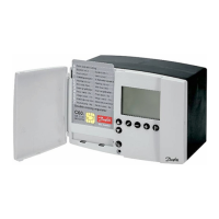
Switching on the OPTYMA
TM
Control single-phase
After wiring the electronic controller correctly,
connect 230 V a.c.; the display panel will
immediately emit a beep and all the LEDs will come
on simultaneously for a few seconds.
Compressor activation/deactivation conditions
The OPTYMA
TM
Control single-phase activates the
compressor when cold room temperature exceeds
setting+dierential (r0); it deactivates the
compressor when the cold room temperature is
lower than the setting.
Manual defrosting
To defrost just press the dedicated key (see page 8)
to activate the elements relay. Defrosting will not
take place if the end-of-defrost temperature setting
(d2) is lower than the temperature detected by the
evaporator sensor. Defrosting ends when the end-
of-defrost temperature (d2) or maximum defrost
time (d3) is reached.
When using data communication, the defrost cycle
can be started from the system unit.
 Loading...